Radial cascade air compressor

A compressor and runoff technology, used in radial flow pumps, gas turbine devices, mechanical equipment, etc., can solve problems such as failure to achieve compression ratio, interference compression, small compression ratio, etc., achieve a large range of design changes, and ensure manufacturing accuracy. , the effect of higher compression

Inactive Publication Date: 2006-10-18
刘昌喆
View PDF0 Cites 11 Cited by
  • Summary
  • Abstract
  • Description
  • Claims
  • Application Information

AI Technical Summary

Problems solved by technology

The designs of existing small aviation jet engines all use centrifugal compressors. However, centrifugal compressors only rely on the centrifugal force of free-rotating gas to compress, and their compression ratio is very small, and their efficiency is very low. The type compressor is barely suitable for the engine in the avionics generator
However, another type of compressor commonly used in existing aviation jet engines—the axial flow cascade compressor, because the direction of the centrifugal force is inconsistent with the airflow compression direction, the centrifugal force will interfere with the compression, and the axial flow cascade compressor cannot be made into a small size , the processing and installation of small-sized blades are very difficult, so the axial-flow cascade compressor is only suitable for large and medium-sized aviation jet engines and large aircraft

Method used


Image

  • Radial cascade air compressor
  • Radial cascade air compressor
  • Radial cascade air compressor

Examples


Embodiment Construction

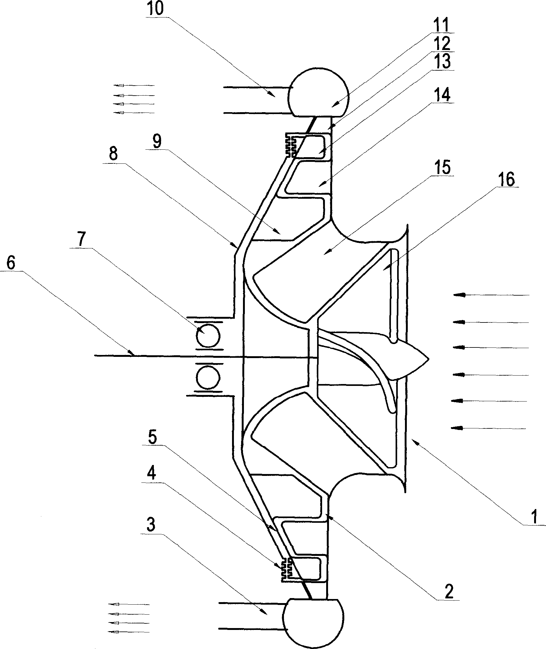
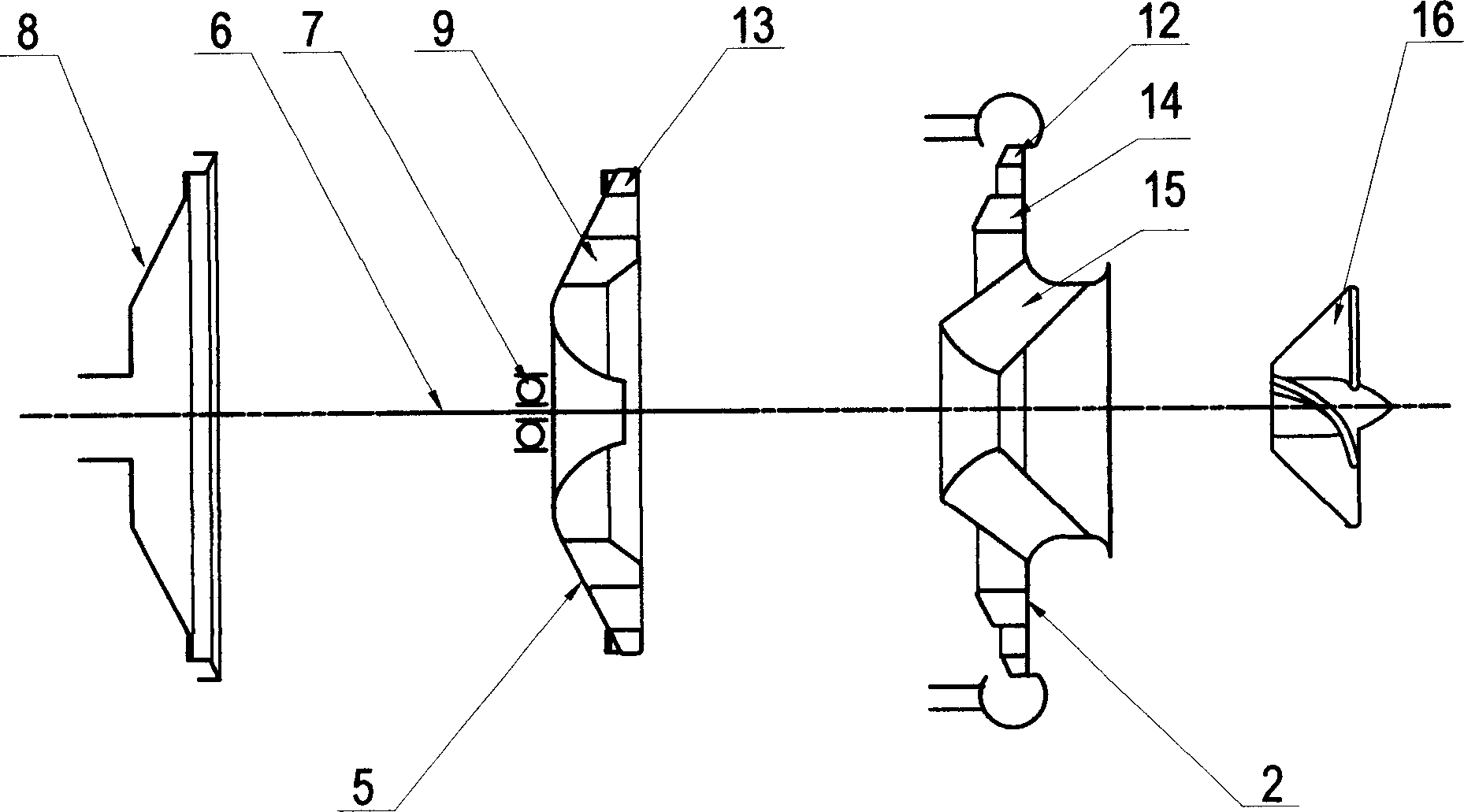
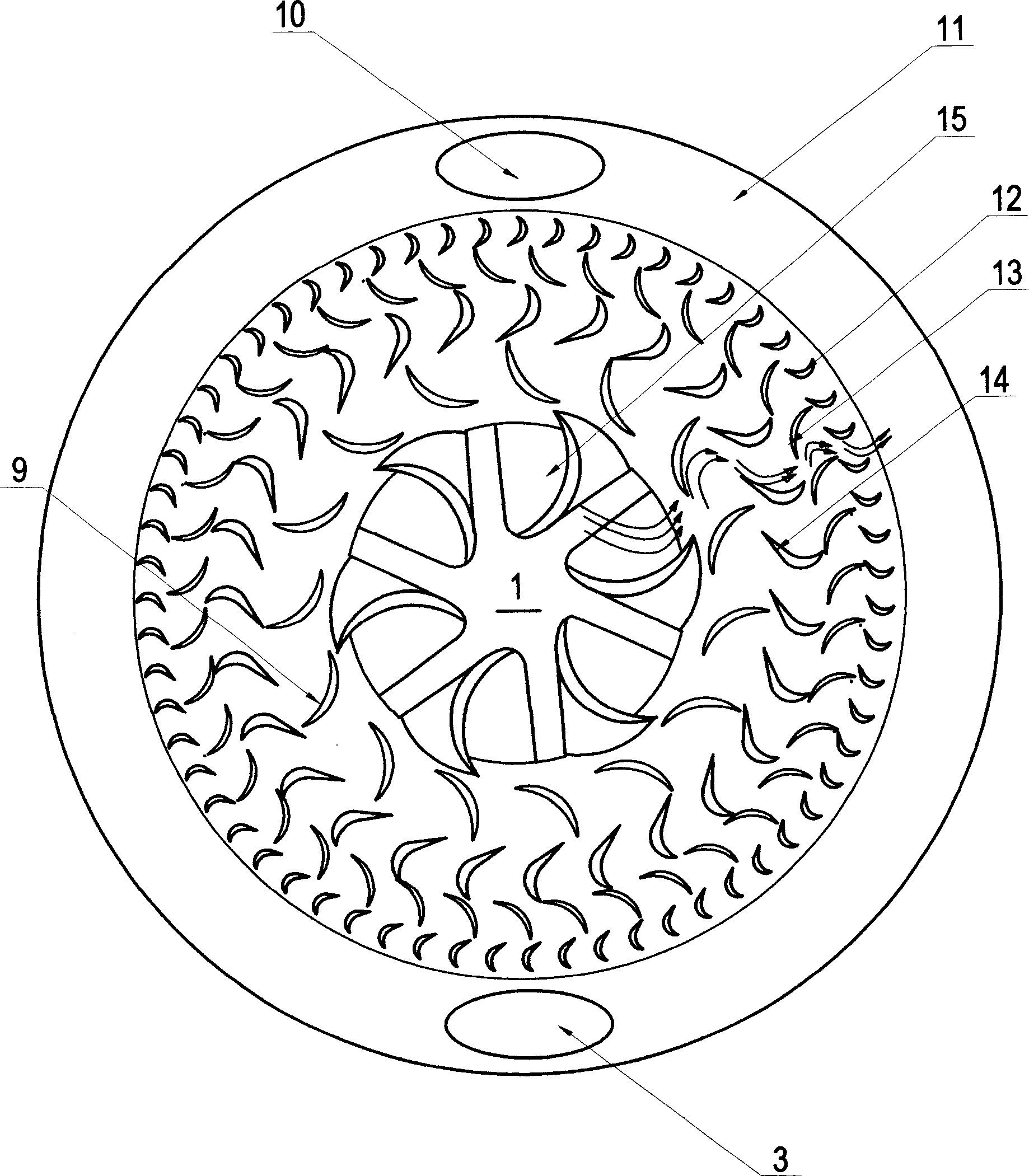
[0017] see Figure 1 to Figure 3 , which is a preferred embodiment of the present invention, the radial cascade compressor mainly includes an air inlet 1 located in the center, a stationary blade disk 2, a moving blade disk 5, a rear cover 8, an annular pressure collecting chamber 11 and an axial Compression impeller 16.

[0018] The stationary vane disc 2 is in the shape of a disc, on which are arranged a number of stationary vanes 12, 14 arranged in a concentric ring shape, and the stationary vanes 12, 14 form an annular stationary vane cascade, which is adjacent to the stationary vane disc 2 At the position of the air inlet 1 , an annular stationary vane cascade 15 is also provided, and the blade shape of the annular stationary vane cascade 15 is a space helicoid.

[0019] The moving blade disk 5 is provided with a number of moving blades 9, 13 arranged in concentric rings, and the moving blades 9, 13 form an annular moving blade cascade; the outer circular area of ​​the m...


PUM


Abstract

The present invention relates to one kind of radial cascade air compressor, which includes air inlet in the axis, shell, movable vane disc and static vane disc. The movable vane disc and the static vane disc have concentrically arranged movable vanes and static vanes separately to form movable cascade and static cascade. The movable vane disc and the static vane disc are installed oppositely, and movable cascade and the static cascade are separated mutually. While the movable vane disc rotates, air sucked through the air inlet is compressed radially outwards before being exhausted via the passage. The present invention is superior to axial cascade air compressor, and has relatively high compression rate, wide design variance range and other advantages, and possesses absolute advantage in flat aeroengine and small airplane vortex jet engine.

Description

【Technical field】 [0001] The invention belongs to the field of aviation turbojet engines, in particular to a radial cascade compressor applied to aviation turbojet engines. 【Background technique】 [0002] The compressor is one of the important components of the aviation turbojet engine. Its function is to compress the airflow entering the engine. The intake compression process is a necessary process of the thermodynamic cycle of the aeroengine. The compression ratio is the most important element that determines the engine power. The designs of existing small aviation jet engines all use centrifugal compressors. However, centrifugal compressors only rely on the centrifugal force of free-rotating gas to compress, and their compression ratio is very small, and their efficiency is very low. Type compressors are barely suitable for engines in avionics generators. However, another type of compressor commonly used in existing aviation jet engines—the axial flow cascade compressor,...

Claims


Application Information

Patent Timeline
Patent Type & Authority Applications(China)
IPC IPC(8): F04D17/00F02C6/04
CPCF04D17/127F02C3/05
Inventor 刘昌喆
Owner 刘昌喆
Why Eureka
Try Eureka