
Energy-saving control loop of hydraulic system

A hydraulic system and energy-saving control technology, which is applied to fluid pressure actuation system components, fluid pressure actuation devices, servo motors, etc., can solve problems such as energy waste, achieve low cost, reduce heat dissipation, and reduce production and usage costs Effect

Inactive Publication Date: 2006-10-18
徐州工程机械科技股份有限公司徐工研究院
View PDF0 Cites 3 Cited by
  • Summary
  • Abstract
  • Description
  • Claims
  • Application Information

AI Technical Summary

Problems solved by technology

[0003] Most of the hydraulic circuits mentioned above adopt the structure in which the hydraulic pump is directly connected to the engine. As long as the engine is running, the energy consumption of the hydraulic pump cannot be avoided (regardless of whether the mechanical equipment is working or not). The displacement and the system limit the maximum pressure to operate. When the system safety valve is opened, the hydraulic oil is directly discharged into the oil tank, resulting in a great waste of energy.

Method used


Image

  • Energy-saving control loop of hydraulic system

Examples


Embodiment Construction

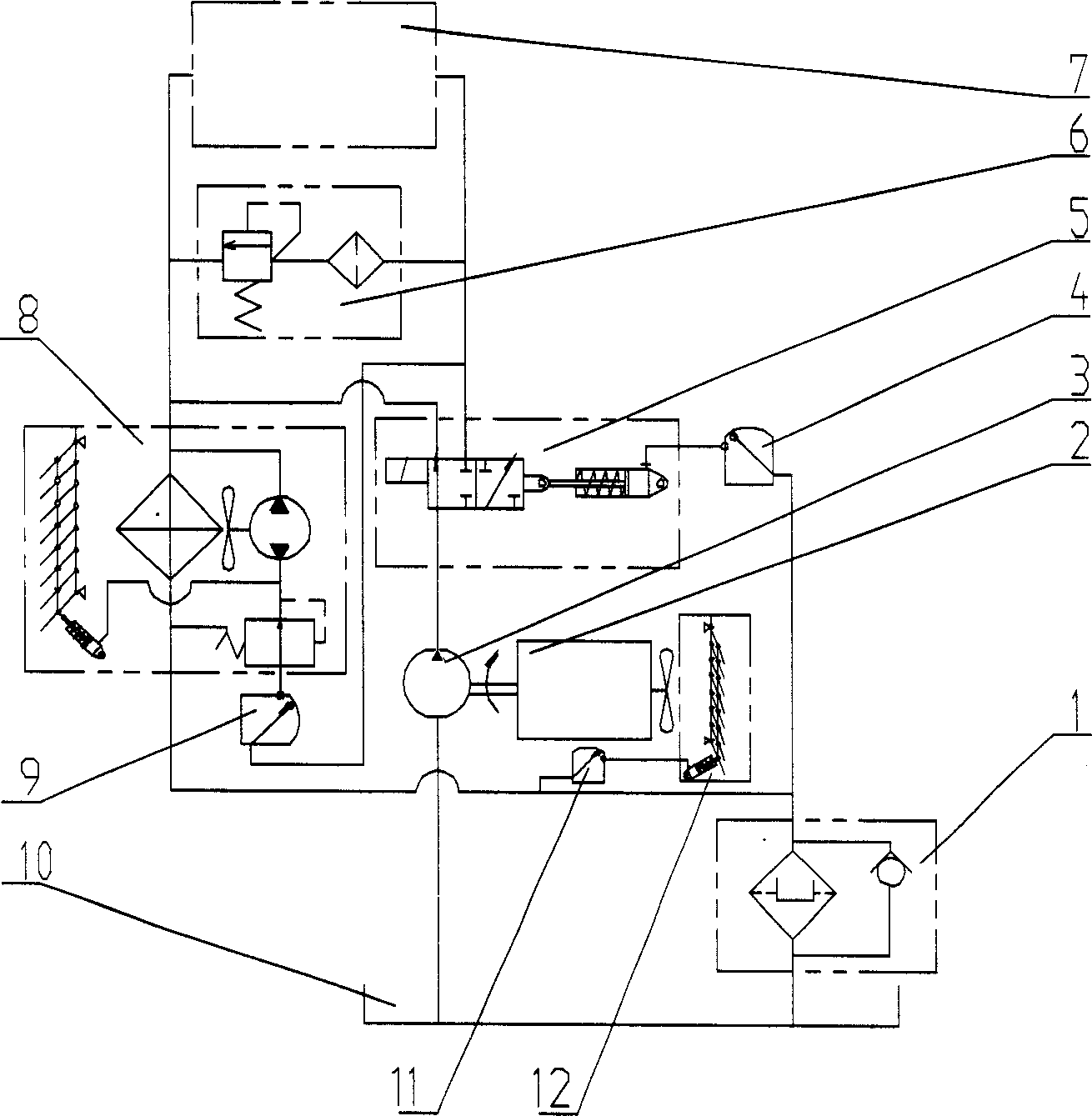
[0010] First, the engine (2) hydraulic pump (3) is connected as a whole and fixed on the base frame of the mechanical equipment, the manual rotary valve (4) is fixed on the operating table of the mechanical equipment, the fuel tank (10), the valve block assembly (5) , Radiator (8), overflow valve (6) are also installed on the base frame of mechanical equipment, ventilation window (12) is installed on the front end of engine (2) cooling water tank, return oil filter (1), temperature control The valve (9) is installed in the fuel tank (10), and the temperature control valve 2 (11) is connected to the engine coolant outflow pipeline; the fuel tank (10), hydraulic pump (3), valve block assembly (5), hydraulic The connection between the main oil circuit (7) and the oil outlet of the valve block assembly (5), the temperature control valve (9), and the high-pressure pipeline between the radiator (8); 8), the connection between the oil return filter (1) and the pipeline between the oi...


PUM


Abstract

The present invention relates to water cooled engine driving hydraulic pump directly and aims at lowering power consumption. The control loop consists of over ten parts, including return oil filter, engine, hydraulic pump, hand cock, etc. as well as pipeline. During idle running of the engine, the valve block assembly feeds the hydraulic oil from the hydraulic pump back to the oil tank through the heat sink and the return oil filter, producing little energy loss. When the equipment is run, the hand cock is first opened, and the pressure the return oil filter produces is utilizes to drive the valve block assembly to commutate, so that pressurized oil from the hydraulic pump fills the whole high pressure pipeline for the equipment to run normally. After the temperature of the hydraulic oil and the engine cooling fluid is raised to certain value, the temperature controlled valve is opened automatically, the ventilating channel to the engine tank and the heat sink is opened and the fan is rotated, so as to cool the hydraulic oil and the engine cooling fluid.

Description

technical field [0001] The invention relates to a hydraulic circuit of construction machinery, which realizes energy saving and consumption reduction to the greatest extent according to the working condition requirements of operating equipment. Since the circuit contains specially set reversing valves, temperature control valves, valve block assemblies and their connecting pipelines, even if the hydraulic pump is integrated with the engine, the engine can still start and run with zero load (very small load in non-construction state) , up to a negligible level). Background technique [0002] Due to the characteristics of small size, light weight, easy layout, convenient pipeline connection and simple maintenance of hydraulic components, hydraulic transmission technology has been widely used in various mechanical equipment at present. Whether it contains hydraulic open loops, closed loops, or quantitative systems and variable systems, modern mec...

Claims


Application Information

Patent Timeline
IPC IPC(8): F15B11/02F15B11/08F15B13/02F15B21/04
Inventor 吴兆成杨力夫马新敏吴永成王渠陈慧
Owner 徐州工程机械科技股份有限公司徐工研究院
Features
  • Generate Ideas
  • Intellectual Property
  • Life Sciences
  • Materials
  • Tech Scout
  • Unparalleled Data Quality
  • Higher Quality Content
  • 60% Fewer Hallucinations
Learn More