Double-walled continuous cooling system

A cooling system and cooling technology, applied in coolers, cooling fluid circulation devices, refrigerated rooms, etc., can solve the problems of high cooling efficiency, unfavorable cooling speed, slow cooling speed, etc., to reduce the generation of frost and achieve good cooling capacity. Effect

Inactive Publication Date: 2006-10-18
TOYO SEISAKUSHO KK
View PDF2 Cites 9 Cited by
  • Summary
  • Abstract
  • Description
  • Claims
  • Application Information

AI Technical Summary

Problems solved by technology

[0010] However, such a double-walled cooling system does not directly cool the room to be cooled by the cooling air, so it cannot be said that the cooling efficiency must be high.
Therefore, the cooling rate is also slower than direct cooling, which is not suitable for quick freezing in essence.
And as mentioned above, continuous cooling is disadvantageous in terms of cooling speed because of the large circulation of outdoor air, and the double-wall cooling system cannot obtain the desired cooling capacity, or the conveyor belt needs to be lengthened, which is the problem.

Method used


Image

  • Double-walled continuous cooling system
  • Double-walled continuous cooling system
  • Double-walled continuous cooling system

Examples


Embodiment Construction

[0026] Embodiments of the double-walled continuous cooling system (hereinafter referred to as the cooling system) of the present invention will be described below.

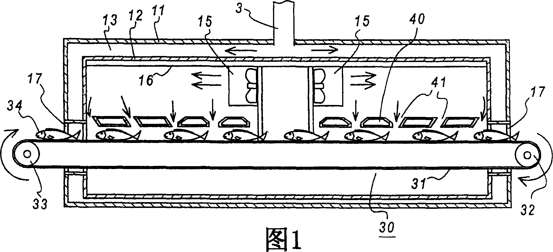
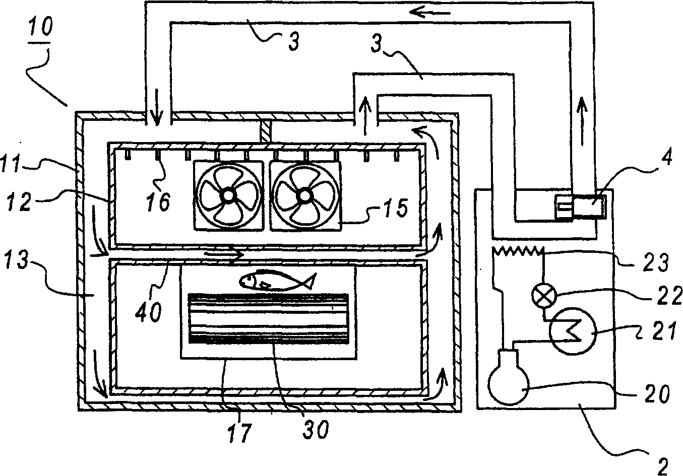
[0027] Fig. 1 is a side sectional view of the cooling system involved in the present embodiment, figure 2 is a front cross-sectional view of the cooling system according to this embodiment.

[0028] Referring first to Figure 1 and figure 2 The overall configuration of the cooling system 1 will now be described.

[0029] Such as figure 2 As shown, the cooling system 1 is roughly composed of a low-temperature medium generating device 2 and a casing 10 . Inside the low-temperature medium generating device 2 , the refrigerant passing through the compressor 20 and the condenser 21 passes through the expansion valve 22 and absorbs heat in the evaporator 23 to cool the cooling medium flowing inside the medium pipeline 3 . As the cooling medium, dry air, salt water, cold water, etc. can be used, but there are also ...


PUM


Abstract

The present invention provides a continuous cooling system which reduces the generation of frost and contamination of food and has good cooling capacity. It has: an outer wall body (11) with low thermal conductivity; an inner wall body (12) with high thermal conductivity; a medium circulation path ( 13) a medium circulation device (4) circulating in the middle; a conveyor device (30) for transporting the cooled product (34) through the cooled chamber (14) as the inner side of the inner wall body (12) from the outside; an air circulation device (15) that circulates the air inside the cooled chamber (14); and a hollow structure (40) disposed near the conveyor device (30), the hollow structure The inside of (40) communicates with the medium circulation path (13).

Description

technical field [0001] The present invention relates to a freezing device for continuously freezing food, fish and shellfish, etc., and particularly relates to a cooling system that does not directly send cooling air into a cooled chamber for cooling. Background technique [0002] Generally speaking, the continuous freezing device has an air cooler and a belt conveyor device in the cooling room, and blows the cooling air from the air cooler to the cooled product conveyed by the conveyor to freeze (unit cooler) forced circulation cooling method) (for example, refer to Patent Document 1). [0003] Figure 5 It is a figure explaining the structure of the conventional continuous freezing apparatus. In the freezing device 100 shown in the drawing, a circulating conveyor 103 for transporting frozen objects is installed between rollers 104 and 104 in a lower box 101 covered with a heat-resistant panel. Air coolers 105 , 105 are provided on the upper case 102 . [0004] In the lo...

Claims


Application Information

Patent Timeline
Patent Type & Authority Applications(China)
IPC IPC(8): F25D17/08F25D13/06
Inventor 吉井一岩尾良雄西田真一平冈祯明园田启之渡部信一郎
Owner TOYO SEISAKUSHO KK
Why Eureka
Try Eureka