Channel decoding and symbol demapping synchronizing method

A channel decoding and de-mapping technology, which is applied in the synchronous field of channel decoding and symbol de-mapping, can solve the problem of not being able to use the ADTB-T system, etc., and achieve the effect of fast capture speed, strong anti-interference ability and large gain

Inactive Publication Date: 2006-10-25
SHANGHAI JIAO TONG UNIV
View PDF2 Cites 4 Cited by
  • Summary
  • Abstract
  • Description
  • Claims
  • Application Information

AI Technical Summary

Problems solved by technology

But this method cannot be used for ADTB-T system which belongs to the category of single carrier

Method used


Image

  • Channel decoding and symbol demapping synchronizing method
  • Channel decoding and symbol demapping synchronizing method
  • Channel decoding and symbol demapping synchronizing method

Examples


Embodiment Construction

[0024] The present invention will be further described below according to the accompanying drawings and specific embodiments

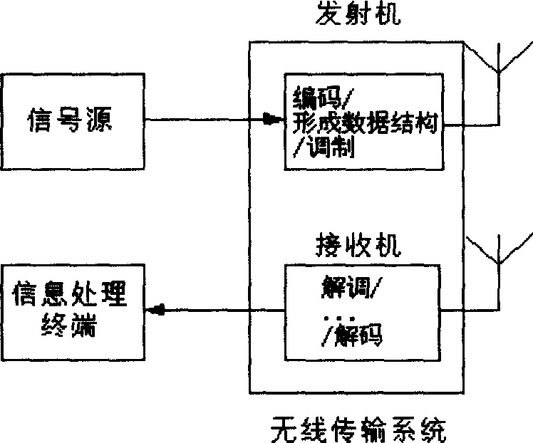
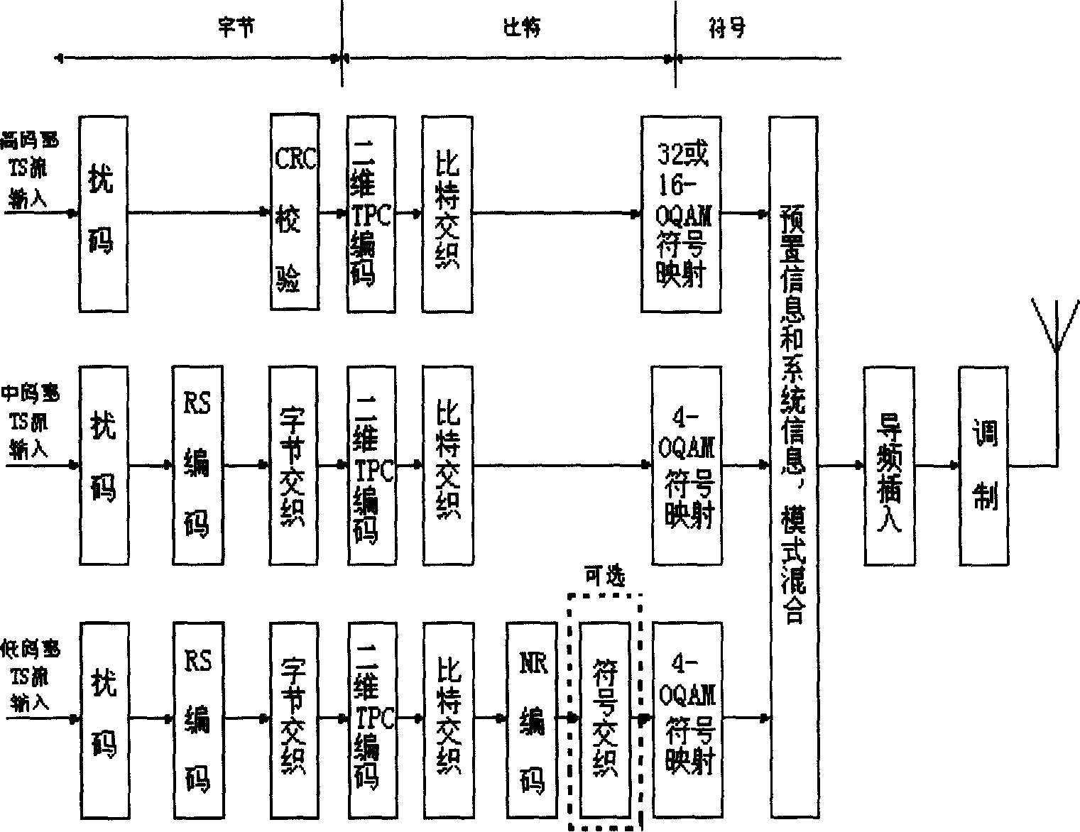
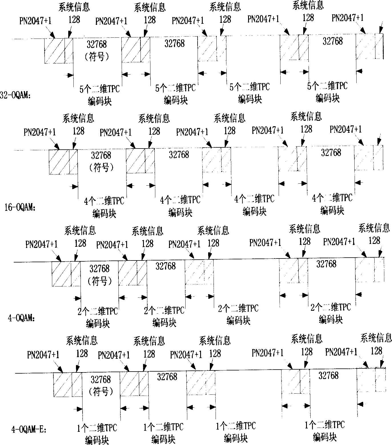
[0025] The synchronization method of channel decoding and symbol demapping of the present invention can be applied to a digital television terrestrial broadcasting system (ADTB-T). What this embodiment discloses is the specific application of the method of the present invention in the ADTB-T system. In the ADTB-T system technical solution applicable to this embodiment, the data stream composed of multi-level symbols transmitted by the transmission system is divided into It is transmitted as a continuous data frame; each data frame contains preset information that can be used for system synchronization, clock recovery, channel estimation and equalizer training, system information that can be used to characterize the data information transmission mode of this frame, and data These three parts of information form a simple first-order cycle.

[0026] In t...


PUM


Abstract

Based on position of preset information, the invention determines original positions of de-mapped channel symbol, decoded channel TPC, decoded channel RS or decoded channel NR. Based on the said original positions, the system realizes synchronization of de-mapped symbol, decoded channel TPC, decoded channel RS and decoded channel NR so as to complete de-mapped symbol, decoded channel TPC, decoded channel RS or decoded channel NR. Since spread spectrum protection is carried out for preset information, entire synchronization process can still be accomplished under condition in larger interference and before equilibrium.

Description

technical field [0001] The invention relates to a method in the technical field of digital signal transmission, in particular to a synchronization method suitable for channel decoding and symbol demapping in digital terrestrial broadcast transmission. Background technique [0002] A wireless transmission system includes a transmitter and a receiver. figure 1 It is a typical system block diagram of digital wireless transmission. The transmission process includes: at the transmitter, first encode the digital signal, and then add necessary auxiliary information, such as synchronization signal, pilot signal, etc.; the encoded digital signal is filtered by the channel A baseband signal is formed; the baseband signal is modulated to a corresponding frequency band by an up-converter and then sent. At the receiving end, if there is a tuner, there is no need for down-conversion. The tuner converts the high-frequency signal to the baseband and then obtains a digital signal through an...

Claims


Application Information

Patent Timeline
Patent Type & Authority Applications(China)
IPC IPC(8): H04L27/26H04H20/00H04L7/00H04L25/02H04N5/04H04N7/015
Inventor 管云峰梁伟强归琳孙军
Owner SHANGHAI JIAO TONG UNIV
Why Eureka
Try Eureka