
Blended light lamp

A technology of light-emitting lamps and incandescent lamps, applied in the field of hybrid light-emitting lamps, can solve the problems of short life and failure of HID lamps

Inactive Publication Date: 2006-10-25
KONINKLIJKE PHILIPS ELECTRONICS NV
View PDF1 Cites 1 Cited by
  • Summary
  • Abstract
  • Description
  • Claims
  • Application Information

AI Technical Summary

Problems solved by technology

Also, the life of HID lamps is very short, which leads to failure of the end result in hybrid luminescent lamps

Method used


Image

  • Blended light lamp

Examples


Embodiment Construction

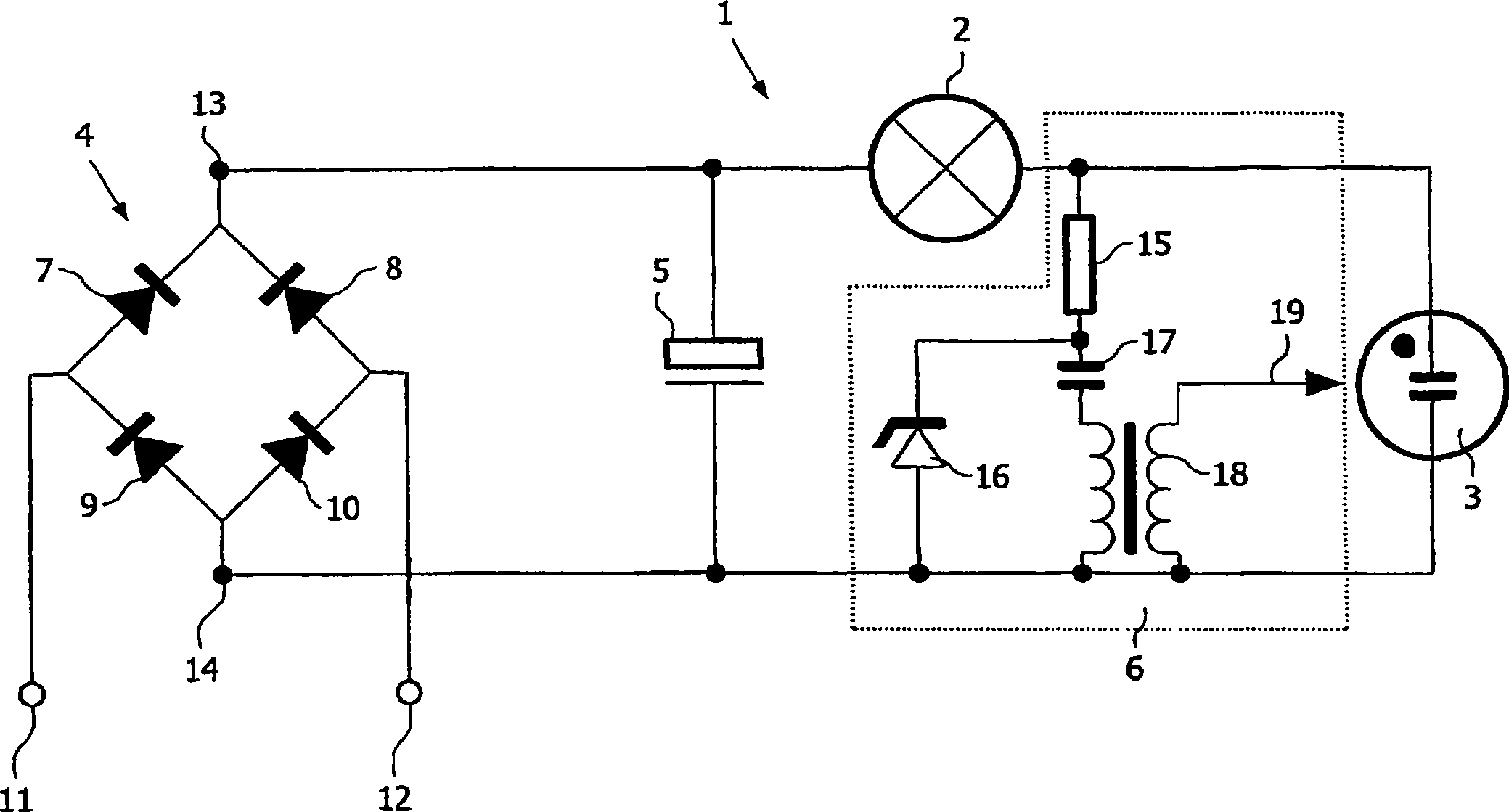
[0018] figure 1 A hybrid lighting lamp 1 with an incandescent lamp 2 , a gas discharge lamp 3 , a rectifier 4 , an energy store 5 and an ignition device 6 is shown. The rectifier 4 has four diodes 7-10 and its input is connected via terminals 11 and 12 to an AC line voltage source. A capacitor 5 acting as an energy store is connected to the outputs 13 and 14 on the secondary side of the rectifier 4 . The incandescent lamp 2 and the gas discharge lamp 3 are connected in series to the outputs 13 and 14 of the rectifier 4 , ie in parallel with the capacitor 5 . A second series circuit comprising the incandescent lamp 2 and the ignition device 6 is also connected to the outputs 13 and 14 . The ignition device 6 comprises a current-limiting resistor 15 , a Zener diode 16 , a capacitor 17 and a coil 18 with an antenna 19 .

[0019] On the primary side, the rectifier 4 is directly connected to the 220V line voltage. On the secondary side, there is a capacitor 5 of 22 uF, to which...


PUM


Abstract

The invention relates to a blended light lamp (1) having an incandescent lamp (2) and a gas discharge lamp (3), a rectifier (4), an energy storage means (5) and an ignition device (6). The high-pressure discharge has an operating voltage of 180 V, which can be achieved by filling a discharge vessel of the gas discharge lamp (3) with, in particular, an amount of mercury of 153 micromole / cm<3>. In this way a high total luminous flux can be obtained in the operating state.

Description

technical field [0001] The invention relates to a hybrid lighting lamp comprising an incandescent lamp, a gas discharge lamp, a rectifier, an energy storage device and an ignition device. Background technique [0002] A simple method of ballasting high pressure discharge lamps takes the form of a hybrid lamp or a single light source. In this case, a tungsten filament, which also acts as an incandescent filament, is connected in series with a high intensity discharge (HID) lamp. A hybrid luminescent lamp of this type is known from DE3224575A1. In order to start a HID lamp and keep it working, there are quite a few electronic circuits that must be operated. Also, the life of HID lamps is very short, which leads to the end result being a failure in hybrid luminescent lamps. Contents of the invention [0003] It is therefore an object of the invention to devise a gas discharge lamp in order to be able to operate the gas discharge lamp with a simple electrical circuit and to...

Claims


Application Information

Patent Timeline
Patent Type & Authority Applications(China)
IPC IPC(8): H05B35/00H01J61/20H05B41/46
CPCH01J61/20H05B35/00H05B41/46
Inventor M·博恩R·约斯特
Owner KONINKLIJKE PHILIPS ELECTRONICS NV
Learn More