Guide rail spline oriented drilling tool

A technology of directional drilling and guide rail, which is applied in directional drilling and other directions, can solve the problems of reducing travel pin wear, force deformation, uneven force, etc., and achieve the effect of reducing travel pin wear and force deformation, intuitive state, and large power

Inactive Publication Date: 2006-11-01
杜炊
View PDF1 Cites 8 Cited by
  • Summary
  • Abstract
  • Description
  • Claims
  • Application Information

AI Technical Summary

Problems solved by technology

[0004] Increase the internal splines and external splines to transmit the WOB, instead of the traveling pin bearing, because the splines are evenly distributed along the axial direction, the force is uniform, it overcomes the disadvantage of uneven force on the single side wall of the traveling pin, and reduces the wear and stress of the traveling pin out of shape

Method used


Image

  • Guide rail spline oriented drilling tool
  • Guide rail spline oriented drilling tool
  • Guide rail spline oriented drilling tool

Examples


Embodiment Construction

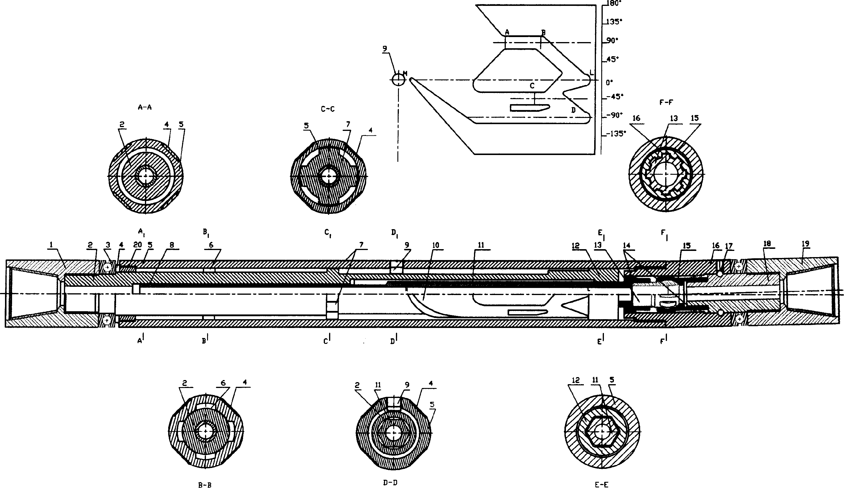
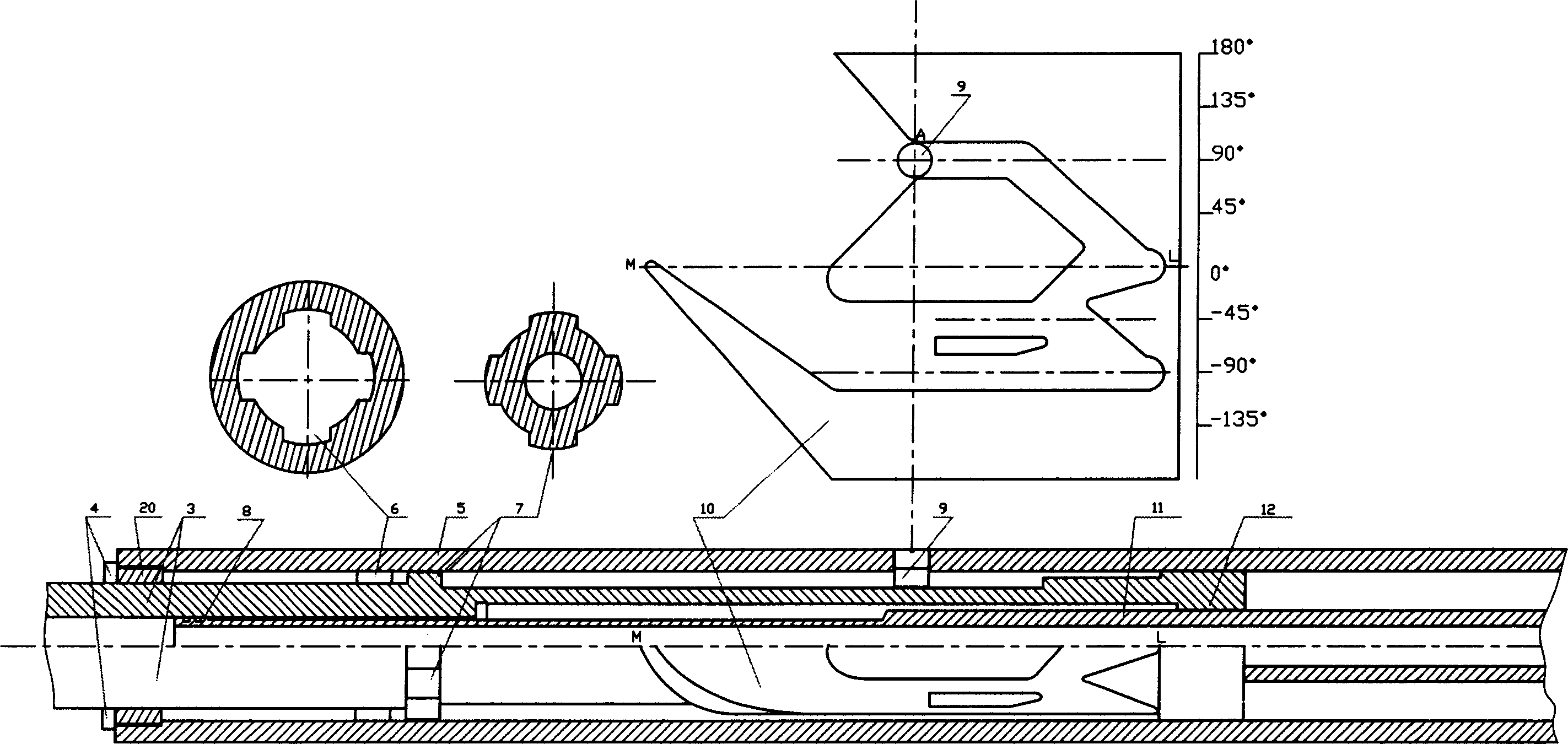
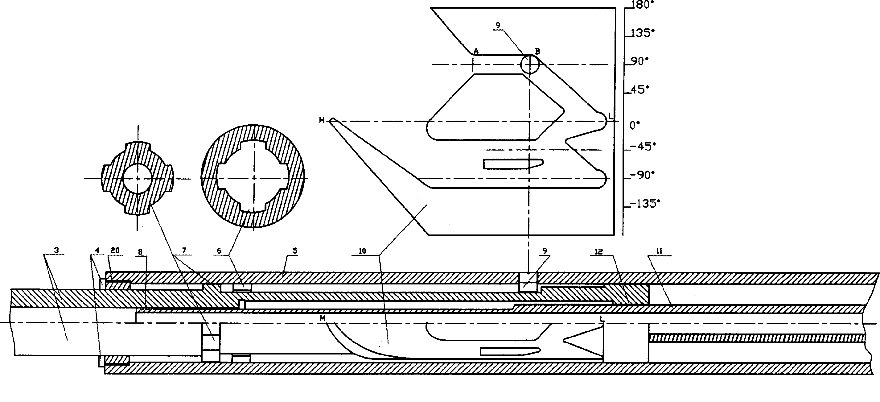
[0022] Working principle of the present invention and embodiment can refer to accompanying drawing: Figure 1 to Figure 6 In the figure, the upper middle is the expanded view of the travel pin guide rail, and the scale on the right side of the expanded view indicates the angle value on the corresponding circle. In the figure, 1 is the upper joint, 2 is the driving shaft, 3 is the thrust bearing, 4 is the spring leaf, 5 is the shell, 6 is the inner spline, 7 is the outer spline, 8 is the floating seal, 9 is the free pin, 10 is a guide rail, 11 is a driven shaft, 12 is an inner hexagon, 13 is an inner ball key, 14 is a sealing ring, 15 is an outer ball key, 16 is a skewer, 17 is a limit bearing, 18 is a connector, 19 is Drill joint, 20 is a sealing assembly, 21 is a flute, and 22 is a welding port.

[0023] figure 2 It is the positional relationship of each component when the floating pin of the drilling tool is lifted to point A.

[0024] image 3 It is the positional rela...


PUM


Abstract

A guide rail spline orientation drill includes a shell, driving shaft, moving pin, moving seal, spring tab, driven shaft, bearing, gimbal joint and whipstock. There is guide rail on the out face of the driving shaft in a one-way circle shape. There is an inner spline on the inner wall of the shell with the same phase to the moving pin. There is an outer spline on the out face of the driving shaft. The inner spline and outer spline could get through the guide rail in case of interlace position, and will transmit drilling pressure in case of overlap position. The drill is driven by rotary disc and capable of substituting screw drill. The drill could work in two manners of angle building and angle holding by raise up or putting down it.

Description

technical field [0001] The invention relates to a directional drilling tool powered by a turntable, which can replace a screw drilling tool for directional wells, long, medium and short radius directional horizontal wells, cluster wells and branch wells in the exploration and development of oil (gas) wells drilling. Background technique [0002] Existing directional horizontal well tools can be referred to as the rotary table rotary directional drilling tool, and the patent No. is 03236776.7. The traditional directional horizontal well tool uses a screw as power. The power of the screw is insufficient and the length is too large. Steady drilling requires repeated tripping and tripping, resulting in a long construction period. The existing short-radius horizontal well tools need to complete deflection build-up and horizontal extension in several trips, and the working efficiency is low. Contents of the invention [0003] The object of the present invention is to provide a...

Claims


Application Information

Patent Timeline
Patent Type & Authority Applications(China)
IPC IPC(8): E21B7/04
Inventor 杜莉婷杜炊
Owner 杜炊
Why Eureka
Try Eureka