Radiating fin and its packing structure

A packaging structure and heat sink technology, applied in the direction of electrical components, electrical solid devices, circuits, etc., can solve problems such as deformation, displacement, damage, etc.

Active Publication Date: 2006-11-01
ADVANCED SEMICON ENG INC
View PDF0 Cites 11 Cited by
  • Summary
  • Abstract
  • Description
  • Claims
  • Application Information

AI Technical Summary

Problems solved by technology

[0008] The purpose of the present invention is to overcome the problem that the heat sink used in the existing packaging process is easy to bend inward due to the pressure of the sealing mold during the sealing process, and then press the metal wire to deform, shift or even damage it. problem, and to provide a heat sink with a new structure and its packaging structure, the technical problem to be solved is to make the packaging process using this heat sink not compress the metal wires below during the sealing process, thus improving the packaged product. The yield rate, which is more suitable for practical

Method used


Image

  • Radiating fin and its packing structure
  • Radiating fin and its packing structure
  • Radiating fin and its packing structure

Examples


Embodiment Construction

[0048] In order to further explain the technical means and effects that the present invention takes to achieve the intended purpose of the invention, the specific implementation, structure, characteristics and features of the heat sink and its packaging structure proposed according to the present invention will be described below in conjunction with the accompanying drawings and preferred embodiments. Its effect is described in detail below.

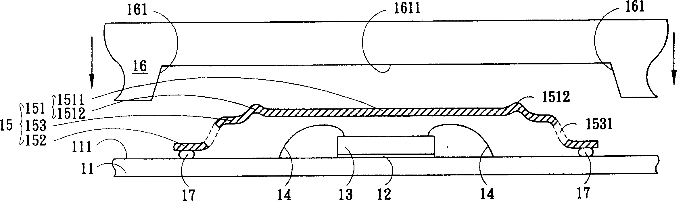
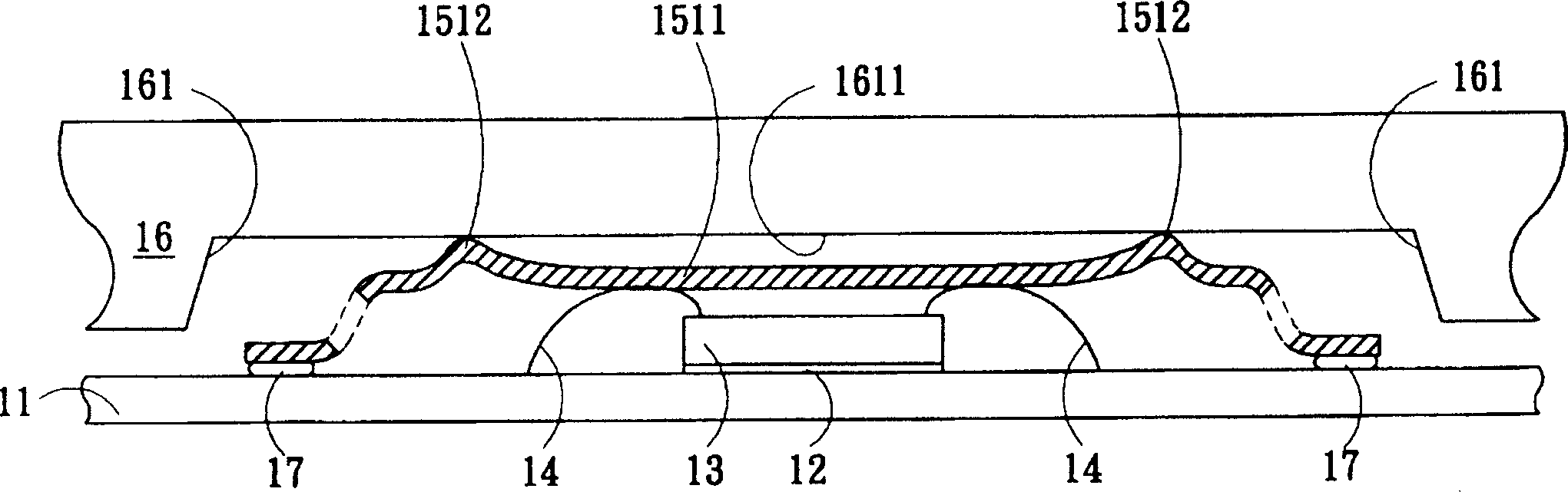
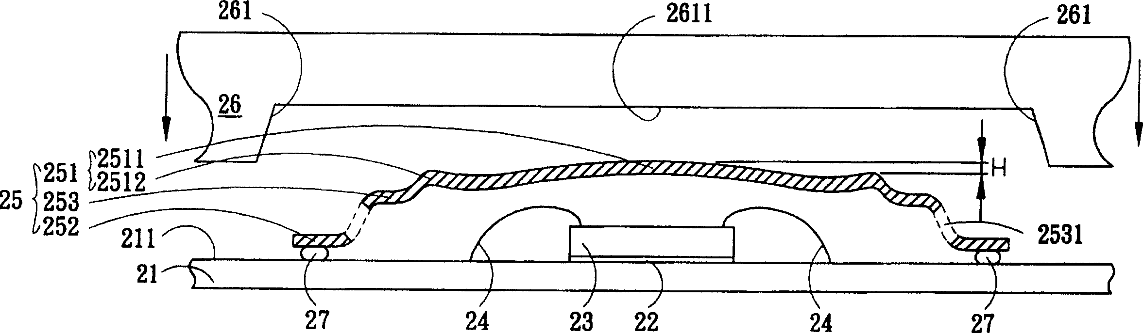
[0049] Embodiments of the present invention are described in detail as follows with schematic diagrams. When describing the embodiments of the present invention in detail, the annular protrusions of the heat sink and the arc shape of the circular plate portion will be enlarged and displayed and explained. Take this as a limited cognition. In addition, the composition and operation mechanism of the carrier substrate, chip, metal wire, and heat sink used in the above-mentioned packaging process should also include other necessary parts in ...


PUM


Abstract

The heat sink is designed for an encapsulation process and has a round cambered surface panel. The height of central part of the round cambered surface is equal or higher than the one of ring- shaped bulge. When the horizontal top side of internal cavity of encapsulation mold is pressed down to the heat sink so as to produce a deformation, the cambered surface can not be pressed to oppress the subjacent metal line, and the ring-shaped bulge can also prevent mold-overflow.

Description

technical field [0001] The invention relates to a heat sink and its application, in particular to a heat sink suitable for packaging process and its application. Background technique [0002] As the integration of IC chips' internal circuits continues to increase, how to effectively and quickly discharge heat has become an important issue in the IC chip packaging process. Therefore, metal heat sinks with high thermal conductivity characteristics are often used. In the packaging process, and during the molding process, the heat sink is directly pasted on the preheated substrate carrying a chip, and then put into the molding mold together, and then a Molten encapsulation compound such as epoxy resin (epoxy molding compound) is pressed into the mold to make it encapsulate (encapsulate) the components in the mold cavity, and then perform other shear molding procedures after cooling. [0003] It is known that in the sealing mold 16, when the heat sink 15 has been attached to the...

Claims


Application Information

Patent Timeline
Patent Type & Authority Applications(China)
IPC IPC(8): H01L23/34H01L23/28
CPCH01L2224/48091H01L2224/73265H01L2924/1815
Inventor 刘俊成
Owner ADVANCED SEMICON ENG INC
Why Eureka
Try Eureka