Encoding method and encoder for tailing convolution codes

A tail-biting convolutional code and decoder technology is applied in the field of error-correcting code decoders, and can solve the problems of difficulty in implementation, high bit error rate, and high computational complexity.

Inactive Publication Date: 2006-11-01
ZTE CORP
View PDF0 Cites 21 Cited by
  • Summary
  • Abstract
  • Description
  • Claims
  • Application Information

AI Technical Summary

Problems solved by technology

[0009] The technical problem to be solved by the present invention is to provide a tail-biting convolutional code decoding method and its decoder, wh...

Method used


Image

  • Encoding method and encoder for tailing convolution codes
  • Encoding method and encoder for tailing convolution codes
  • Encoding method and encoder for tailing convolution codes

Examples


Embodiment Construction

[0047] The purpose of the present invention is to overcome the relatively high complexity of the existing tail biting convolutional code decoding method, which is relatively difficult to implement, especially in real-time communication that requires relatively high decoding speed. A decoding method for tail biting codes proposed by the present invention has lower computational complexity compared with currently available methods.

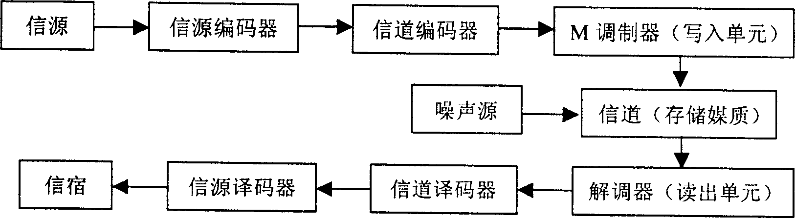
[0048]Tailbiting code decoders are different from ordinary decoders in that they need to predict the initial state. Once this state is obtained, they can be regarded as ordinary decoders. An equivalent statement is that it must correctly identify any state in the trellis diagram, and once correct, ordinary Viterbi decoding can be performed.

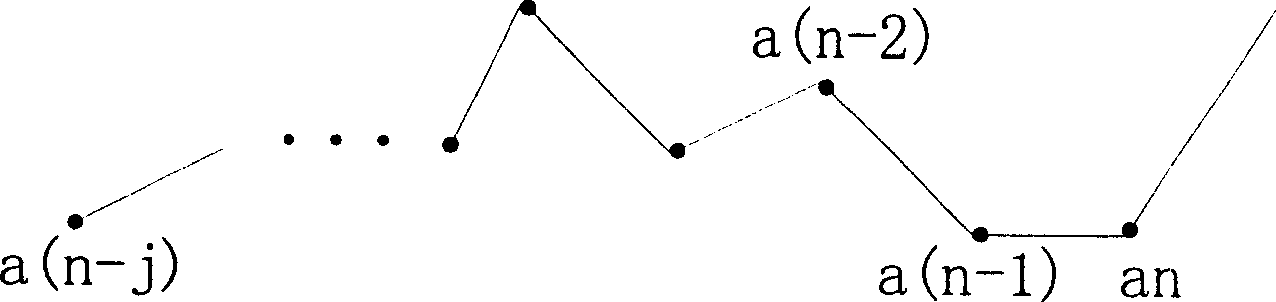
[0049] In order to clearly describe the implementation process of this method, the present invention needs to accurately define several concepts and three decision depth parameters (decision depth), which are a...


PUM


Abstract

The invention comprises the following steps: with the accumulating metrics of the initial window, an incorrect initial path is merged into a correct path, and a state of optimal node at the end of initial window is used as a decoding initial state of the tail-biting convolution code; in term of said decoding initial state and a delay window, through whole decoding trace-back, a Viterbi decoding is made for the tail-biting convolution code.

Description

technical field [0001] The present invention relates to a decoder for error correction codes widely used in digital communication systems, in particular to a new decoding method and decoder for tail biting convolutional codes. Background technique [0002] All digital communication systems such as communications, radar, remote control and telemetry, digital computer storage systems and internal operations, and data transmission between computers can be summarized as follows: figure 1 The model shown. [0003] figure 1 The source coder is to improve the effectiveness of transmission, and the channel coder is to fight against various noises and interferences in the transmission process. By artificially adding redundant information, the system has the ability to automatically correct errors, thus Guarantee the reliability of digital transmission. With the development of wireless digital communication and the emergence of various high-speed and bursty services, people put for...

Claims


Application Information

Patent Timeline
IPC IPC(8): H03M13/23
Inventor 曾立徐俊袁柳清
Owner ZTE CORP
Why Eureka
Try Eureka