Electric chuck unit

An electric chuck and chuck technology, applied in the field of machinery, can solve the problems of dynamic balance, complex structure, difficult installation and maintenance, etc., achieve the effect of reducing mass, simple and compact structure of the device, and improving the quality of dynamic balance

Inactive Publication Date: 2006-11-08
CHONGQING UNIV
View PDF1 Cites 12 Cited by
  • Summary
  • Abstract
  • Description
  • Claims
  • Application Information

AI Technical Summary

Problems solved by technology

[0003] The present invention proposes an electric chuck device in order to overcome the deficiencies of

Method used


Image

  • Electric chuck unit
  • Electric chuck unit
  • Electric chuck unit

Examples


Embodiment Construction

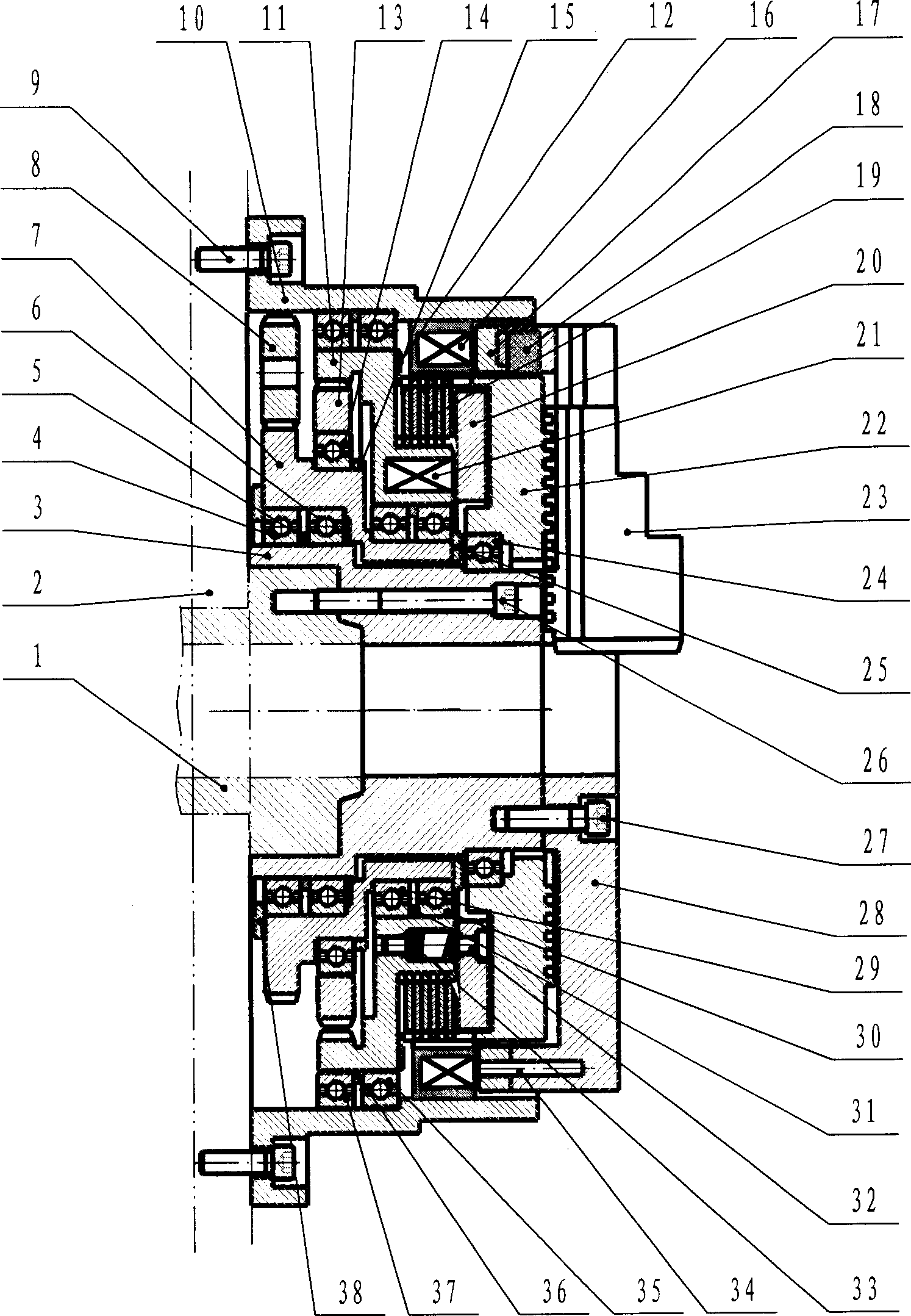
[0025] figure 1 In the structure shown, when the chuck clamps (or loosens) the workpiece, the electromagnetic brakes 16, 17, 34 are energized to act and brake, that is, the electromagnet group 16 is energized to attract the brake ring 17, so that the chuck The body shell 10, the chuck end cover 28, the chuck seat 3, and the main shaft 1 are connected as a whole without rotation; at this time, when the chuck motor (not shown) connected with the gear 8 rotates, the external meshing gear pair 7,8 Move according to the transmission ratio, and the gear 7 is used as an input part and transmits the motion to the internal gear 11 through the gear 13 installed on its eccentric shaft; at the same time, the electromagnetic friction clutch assembly 12, 19, 20, 21 is powered by the slip ring 11 , 32, 33 are energized and act, that is, the electromagnet 21 is energized and the pressure ring 20 is pressed against the friction plate group 19, and the coil wire 22 rotates synchronously with th...


PUM


Abstract

The present invention relates to universal fixture widely used in machine manufacturing field, and is one kind of electric chuck unit. The electric chuck unit consists of a clamping unit, a power unit, an electromagnetic friction clutch assembly, a casing, an electromagnetic brake assembly, etc. When the electromagnetic brake assembly is powered, the clamping unit is connected to the head stock integrally without rotating; and when the electromagnetic friction clutch assembly is powered, the power unit transfers the rotation to the claws for clamping or unclamping the workpiece. During machining, only the clamping unit rotates with the main shaft. Compared with available technology, the present invention has the advantages of reduced rotating part number and weight, being favorable to raising the dynamic balance quality of the main shaft, etc.

Description

technical field [0001] The invention relates to a general fixture for clamping workpieces widely used in the mechanical field. Background technique [0002] Power chucks are often used on CNC lathes and automatic lathes. In addition to hydraulic power chucks and pneumatic power chucks, electric chucks are also widely used. At present, the structure of most electric chucks is as follows: the chuck body is installed at the front end of the main shaft of the lathe, and the motor is installed at the rear end of the main shaft. Can clamp and loosen the workpiece. Patent WO9951380 discloses an electric chuck device. A harmonic gear reducer is installed in the chuck body at the front end of the main shaft of the lathe, and an electric power unit is installed at the rear end of the main shaft, including a motor and an electromagnetic clutch. connected by a hollow shaft. During the machining process, the chuck body, reducer, hollow shaft, main shaft and motor rotor rotate as a who...

Claims


Application Information

Patent Timeline
IPC IPC(8): B23B31/28
Inventor 陈小安陈昶
Owner CHONGQING UNIV
Why Eureka
Try Eureka