
Network terminal apparatus in passive light network and data processing method thereof

A passive optical network and network terminal technology, applied in the field of network terminal devices, can solve problems such as difficulty, low speed, and inability to realize dynamic bandwidth sharing, and achieve the effect of high-speed connection

Active Publication Date: 2010-05-05
HUAWEI TECH CO LTD
View PDF6 Cites 0 Cited by
  • Summary
  • Abstract
  • Description
  • Claims
  • Application Information

AI Technical Summary

Problems solved by technology

[0007] At present, the speed of the equipment using the Ethernet interface as the uplink interface of the home gateway is generally 10Mbps, 100Mbps, and the current maximum is 1000Mbps; while the speed of the equipment using the DSL, HFC, ISDN uplink interface is even lower, generally not exceeding 50Mbps. Compared with the equipment using PON interface as the uplink interface, the speed is too low;
[0008] (2) The service quality that can be provided by network terminals using the above interfaces, such as home gateways, is low;
[0009] The services that home gateways can provide include telephone voice, video, and data access services. Due to the impact of the current uplink interface on the quality of service and service category provided by current home gateways, these services cannot be provided with high quality. Do some business in this area;
[0010] (3) Using the above interface makes user bandwidth allocation difficult to realize:
[0011] In a network terminal network that uses Ethernet ports, xDSL, HFC, and ISDN as uplink interfaces, it is not easy to form an efficient and unified protocol for management among various terminals. There is basically no control coordination between terminals. Each terminal The bandwidth of the network is basically fixed, and the dynamic sharing of bandwidth cannot be realized, resulting in a waste of bandwidth at one network terminal and insufficient bandwidth at another network terminal;
[0012] (4) The distance between the network and the network is short to realize the connection:
[0013] In a network terminal network that uses Ethernet ports, xDSL, HFC, and ISDN as uplink interfaces, the distance from the network terminal to the corresponding Ethernet ports, xDSL, HFC, and ISDN servers is relatively short, and multiple server offices must be used for relay to achieve long-distance transmission, which results in huge cost expenditures in both technology and maintenance
[0014] Therefore, if the various interfaces described in the prior art are used as the uplink interface of the network terminal, it is obviously unable to meet people's increasingly high communication quality requirements

Method used


Image

  • Network terminal apparatus in passive light network and data processing method thereof
  • Network terminal apparatus in passive light network and data processing method thereof

Examples


Embodiment Construction

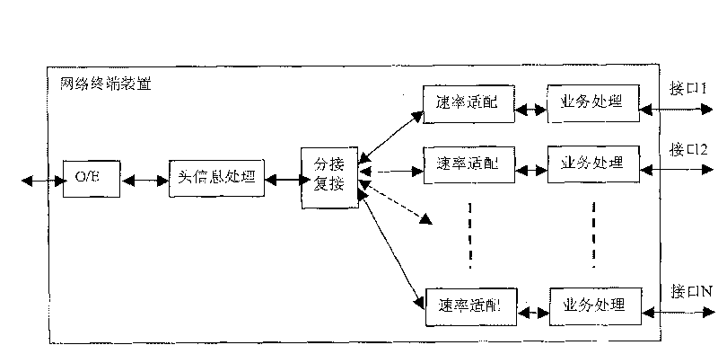
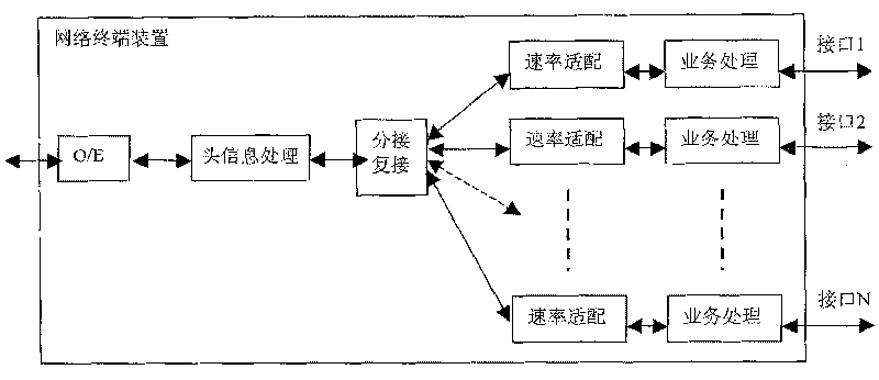
[0047] The core of the present invention is to provide users with a network terminal device in a passive optical network as a user terminal, so that the superior transmission performance of the passive optical network can be extended to the user terminal.

[0048] Specifically, the present invention integrates xPON (various passive optical network technologies) technology and user terminals such as network terminals through various user interfaces (such as Ethernet interfaces) of the passive optical network, thereby integrating the ONU in the xPON technology ( Optical Network Unit) or the user interface of ONT (Optical Network Terminal) is directly connected to the uplink interface of the user terminal, so that the uplink optical interface of ONU or ONT can be directly used as the uplink interface of various network terminals to realize the network terminal and High-speed connection of the network, while using the bandwidth allocation strategy in xPON to allocate bandwidth for ne...


PUM


Abstract

The invention relates to the net terminal device of the passive light net and the data processing method. The invention can melt the passive light net technology with the net terminal through all kinds of the user connecting gob of the passive light net, the ONU of the passive light net technology or the user connecting gob of the ONT can be connected with the upward connecting gob of the user terminal directly, so the ONU or the upward light connecting gob of the ONT are served as the upward connecting gob of the net terminal, the high speed connecting of the net terminal and the net can be realized, at the same time, the band weight allotting game of the passive light net can be used to allot the band weight for the net terminal, and the QQS of the passive light net technology can be used. The invention can make the corresponding net terminal to gain the higher the upward and the downward bandwidth. Bandwidth allocating game of the passive light net technology can be adopted.

Description

technical field [0001] The invention relates to the technical field of optical network communication, in particular to a network terminal device in a passive optical network and a data processing method thereof. Background technique [0002] In a fiber optic network, the fiber optic network unit or fiber optic network terminal communicates with the central fiber optic line unit through PON (passive optical network). The communication protocol can be based on ATM (Asynchronous Transfer Mode) protocol, Ethernet protocol, WDM With technology, etc., it is necessary to realize the Ethernet access, telephone access, video access or dedicated line access required by end users or group users in the optical network unit or optical network terminal. The signals received from the optical fiber network have specific address and transmission rate, in order to realize the user's business in the optical network unit or optical network terminal, it is necessary to perform address mapping, c...

Claims


Application Information

Patent Timeline
Patent Type & Authority Patents(China)
IPC IPC(8): H04B10/12H04L12/56H04L29/06H04Q11/00H04B10/25H04L47/76
Inventor 赵竣李南岭刘昱黄传海谭培龙冯江杨光祥
Owner HUAWEI TECH CO LTD
Learn More