
Non-contact pulp flow pulse reducer for high-speed paper machine approach flow system

A non-contact, high-speed paper machine technology, applied in the direction of paper machine, paper machine wet end, pipeline system, etc., can solve the problems of little influence, complex structure, and reduced inhibition, and achieve easy replacement, simple device structure, Good effect

Inactive Publication Date: 2006-11-22
SOUTH CHINA UNIV OF TECH
View PDF0 Cites 5 Cited by
  • Summary
  • Abstract
  • Description
  • Claims
  • Application Information

AI Technical Summary

Problems solved by technology

[0004] In the non-contact pulse reducer, there is an elastic element between the slurry flow and the air chamber, and the elastic element is used to suppress the pulse. This reducer is installed in the pipeline, and there is a porous partition between the air chamber and the slurry, and a foam glue stick and other elastic components, because the pulp flow of the non-contact reducer does not directly contact with the compressed air, it has little influence on the various links of the subsequent papermaking process, but the structure of the existing non-contact pulse reducer is complex, due to the pulp The cross-section of the region where the device acts suddenly decreases, resulting in an increase in the flow of the pulp flow, which strengthens the pulsation and reduces the suppression effect. Therefore, the design and development of a non-contact pulp flow pulse reducer with a simple structure and obvious effect has a great impact on the flow of the high-speed paper machine. The conveying system has the function of eliminating pulse and stabilizing the slurry flow

Method used


Image

  • Non-contact pulp flow pulse reducer for high-speed paper machine approach flow system
  • Non-contact pulp flow pulse reducer for high-speed paper machine approach flow system

Examples


Embodiment Construction

[0019] The present invention will be described in further detail below with reference to the accompanying drawings and examples, but the embodiments of the present invention are not limited thereto.

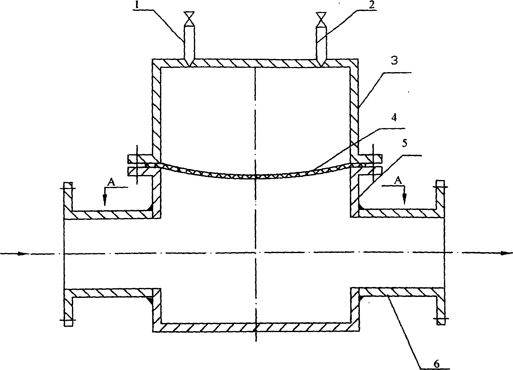
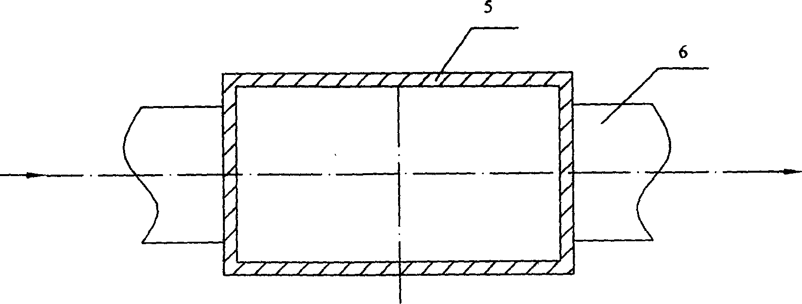
[0020] like figure 1 As shown, a non-contact pulp flow pulse reducer for the high-speed paper machine flow delivery system includes an air chamber 3, an elastic rubber diaphragm 4, and a suddenly expanded rectangular pulp stabilization pipe 5. The two-stage pulp flow pipe The cross-sectional area of ​​the suddenly expanding rectangular slurry-stabilizing pipe 5 connected to the road 6 is greater than the cross-sectional area of ​​the slurry flow pipeline 6, and the suddenly expanding rectangular slurry-stabilizing pipe 5 lower ends are closed, and the upper end is connected to the air chamber 3, and the suddenly expanding rectangular slurry-stabilizing pipe 5 is connected to the An elastic rubber diaphragm 4 is arranged between the air chambers 3 , and the air chambers 3 are resp...


PUM


Abstract

The invention discloses a non-touching slurry pulse destructor in the high-speed paper flow transmitting system, which comprises the following parts: air chamber, elastic rubber diaphragm, two-segmented slurry pipe connecting rapid-expanding rectangle slurry-stable pipe, wherein the cross-sectional area of rapid-expanding rectangle slurry-stable pipe is larger than slurry pipe's; one end of rapid-expanding rectangle slurry-stable pipe is closed and the other end connects air chamber; the elastic rubber diaphragm is set between rapid-expanding rectangle slurry-stable pipe and air chamber, which connects inlet and outlet pipe separately. The invention adds rectangle slurry-stable pipe to increase bulk, which can control action according to real working condition due to air chamber.

Description

technical field [0001] The patent of the present invention relates to the field of pulping and papermaking equipment and technology, in particular to a pulp flow pulse reduction device, in particular to a non-contact pulp flow pulse reducer for a high-speed paper machine flow delivery system. Background technique [0002] In order to prevent the pulp flow entering the headbox from having pressure or speed pulses, the flow delivery system of the high-speed paper machine must consider eliminating the pulses in the pulp flow. The work has little effect, because the air layer above the pulp in the headbox can inhibit the pulse, but on a high-speed paper machine with a fully enclosed full-flow or hydraulic headbox, the pulse of the pulp flow will cause paper web quantification. fluctuations. The pulp flow pulse in the paper machine flow delivery system is mainly caused by the pulse generated by the pump and the rotor screen. Secondly, the air accumulatio...

Claims


Application Information

Patent Timeline
IPC IPC(8): D21F1/06F17D1/20
Inventor 陈克复陈奇峰杨仁党李军莫立焕
Owner SOUTH CHINA UNIV OF TECH
Learn More