Fuel ignition electronically-controlled circuit of automobile engine

An automobile engine and electronic control technology, applied in the direction of automatic control, automatic control, electrical automatic control, etc., to achieve good stability, improve ignition success rate and service life, and the effect of simple components

Inactive Publication Date: 2006-11-22
李延军
View PDF0 Cites 1 Cited by
  • Summary
  • Abstract
  • Description
  • Claims
  • Application Information

AI Technical Summary

Problems solved by technology

[0004] The technical problem to be solved by the present invention is to realize the stability of automobile fuel ignition with a simple circuit, overcurrent and overpressure protection and input signal to cut off the output signal at the same time, so that the engine works without disordered cylinder state, and the ignition order of the automobile engine is guaranteed. Make the engine fuel burn fully, so as to achieve the purpose of saving fuel and reducing vehicle emission pollution

Method used


Image

  • Fuel ignition electronically-controlled circuit of automobile engine
  • Fuel ignition electronically-controlled circuit of automobile engine

Examples


Embodiment 1

[0031] Embodiment 1 The working principle of the automobile engine fuel ignition electronic control circuit of the present invention is described with reference to the accompanying drawings.

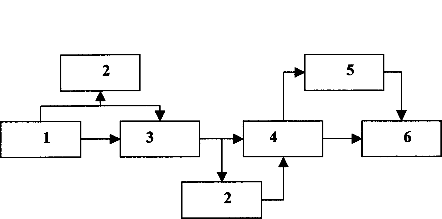
[0032] figure 1 Among them, 1 is the signal input part, 2 is the overvoltage and overcurrent protection circuit, 3 is the shaping detection circuit, 4 is the amplification driving circuit, 5 is the power output shaping circuit, and 6 is the power output part.

Embodiment 2

[0033] Embodiment 2 The circuit parameters of an electronic control circuit for fuel ignition of an automobile engine according to the present invention are given in conjunction with the accompanying drawings.

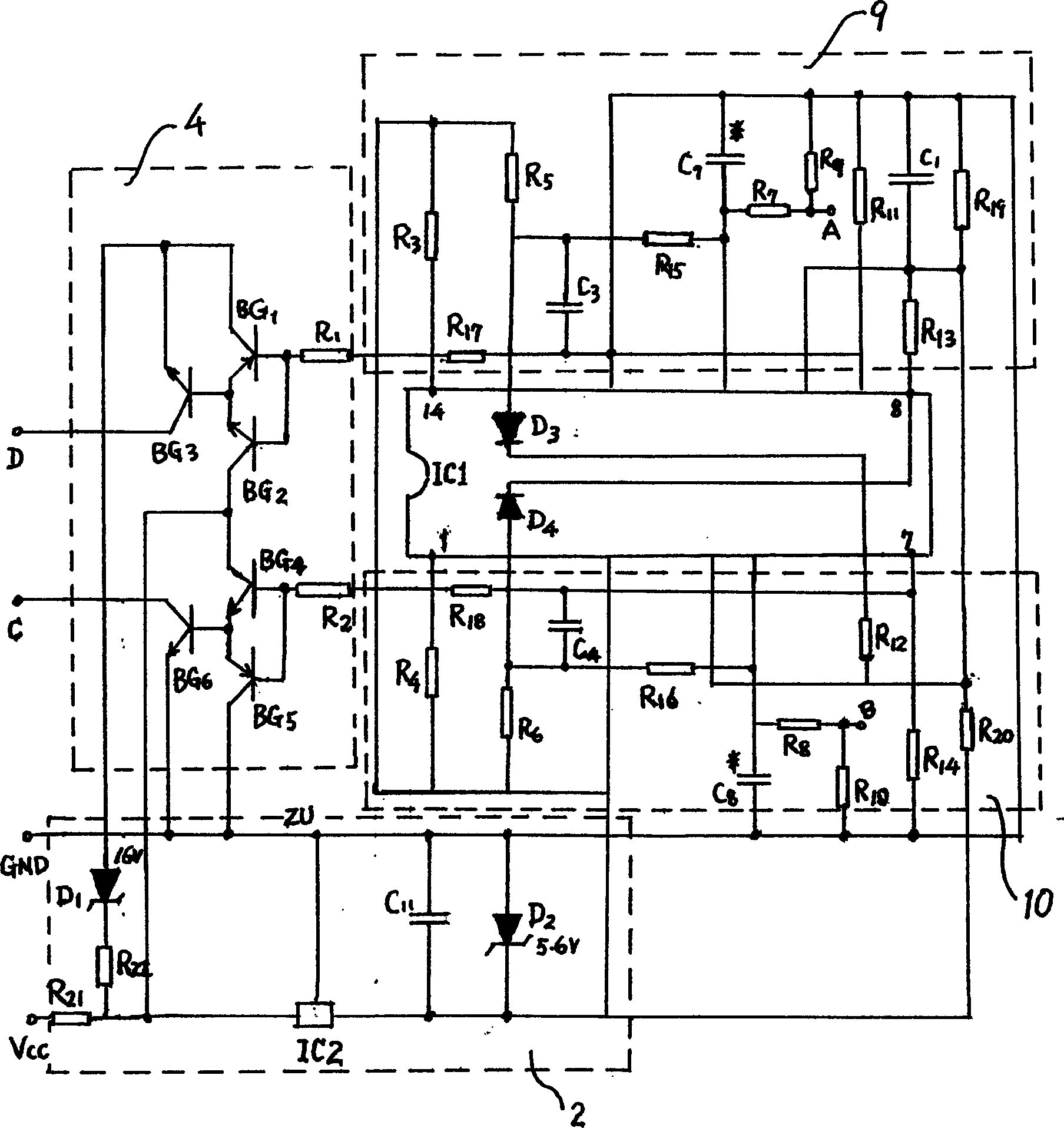
[0034] figure 2 Among them, the amplifying drive circuit 4 consists of six triodes BG 1 , BG 2 , BG 3 , BG 4 , BG 5 , BG 6 Composition, where BG 1 =BG 4 Use 2SD1005, BG 2 =BG 5 Use 2SB1115, BG 3 =BG 6 Use BU941P~Z. amplify the drive circuit through R 1 and R 2 connected with the power output circuit, R 1 =R 2 = 10K.

[0035] C and D connected to the amplifier driving circuit are the signal input part 1 . That is, the two points C and D are the signal input terminals. Signal input section 1 in figure 2 is not drawn with a dotted line.

[0036] The power output shaping circuit 5 is composed of two symmetrical circuits. Among them, each component of power output shaping 1 can adopt the following values: R 3 =3K, R 17 = 2M,R 5 =20K, R 15 = 1M, R ...

Embodiment 3

[0040] Embodiment 3 Amplifying and driving circuit

[0041] The amplification driving circuit 4 may be composed of two IGBT power composite tubes. That is, the triode BG in Embodiment 2 can be replaced by two IGBT power composite tubes respectively1 , BG 2 , BG 3 and BG 4 , BG 5 , BG 6 . This can further simplify the circuit.


PUM


Abstract

The invention discloses a fuel ignite electric control circuit of vehicle engine. Wherein, the signal input part 1 is connected to the computer control box ECU of electric ignition; the over-voltage and over-current protective circuit 2 is formed by diodes D1, D2, the voltage-stabilizer tube IC2, capacitor and resistance; the shaping detecting circuit 3 is formed by diodes D3, D4 and integrated module IC1; the amplify driving circuit 4 is formed by two IGBT power composite tubes; the power output shaping circuit 5 is formed by two symmetry circuits; the power output part 6 is connected to the input of dry ignite coil. The invention has simple elements, stable output wave, and over-voltage over-current protection, while the product has better stability, to ideally control the ejection ignition and improve the service life.

Description

technical field [0001] The invention belongs to the technical field of components of automobile engines, in particular to a control circuit for fuel ignition of automobile engines. Background technique [0002] Automobile safety, energy saving, environmental protection, intelligence and informatization are the development trends of future automobiles. In the development of automobile technology, the role of automobile electronics is particularly prominent, and it is the most important technical measure to develop new models and improve automobile performance. 70% of innovations in automobiles come from automotive electronics. The cost of using automotive electronic devices for each foreign car was 672 US dollars in 1990, and reached 2,000 US dollars in 2000. On some luxury cars, electronics account for more than 50 percent of the vehicle's cost. In the future, the development of automotive electronics will mainly focus on powertrain, chassis control, body control, active an...

Claims


Application Information

Patent Timeline
Patent Type & Authority Applications(China)
IPC IPC(8): F02P5/145
Inventor 李延军姜殿洋黄文
Owner 李延军
Why Eureka
Try Eureka