
Motor-operated valve

An electric valve and motor technology, applied in the direction of lift valve, valve device, valve details, etc., can solve the problems of increasing processing cost, control roughness, contact, etc., and achieve the effect of high-precision control and improvement of decomposition ability

Inactive Publication Date: 2006-11-22
FUJIKOKI MFG CO LTD
View PDF1 Cites 23 Cited by
  • Summary
  • Abstract
  • Description
  • Claims
  • Application Information

AI Technical Summary

Problems solved by technology

[0006] However, in particular, electric valves (used as expansion valves) used in refrigerators and the like control the flow rate of the refrigerant very minutely, but the control is rough in the known technology.
In particular, when using carbon dioxide (gas), etc., there is a problem that the pressure of the refrigerant must be set to a high pressure (about 10 times the conventional ratio). When the interval makes the spool lift, the flow rate of the refrigerant changes too much
However, reducing the pitch of the screw mechanism requires high-precision processing and increases processing costs. In addition, the amount of lift per rotation of the rotor is reduced, and the fixed stoppers and possible stoppers for restricting rotation cannot be properly performed. Problems such as contact and disengagement between brake parts

Method used


Image

  • Motor-operated valve
  • Motor-operated valve
  • Motor-operated valve

Examples


Embodiment Construction

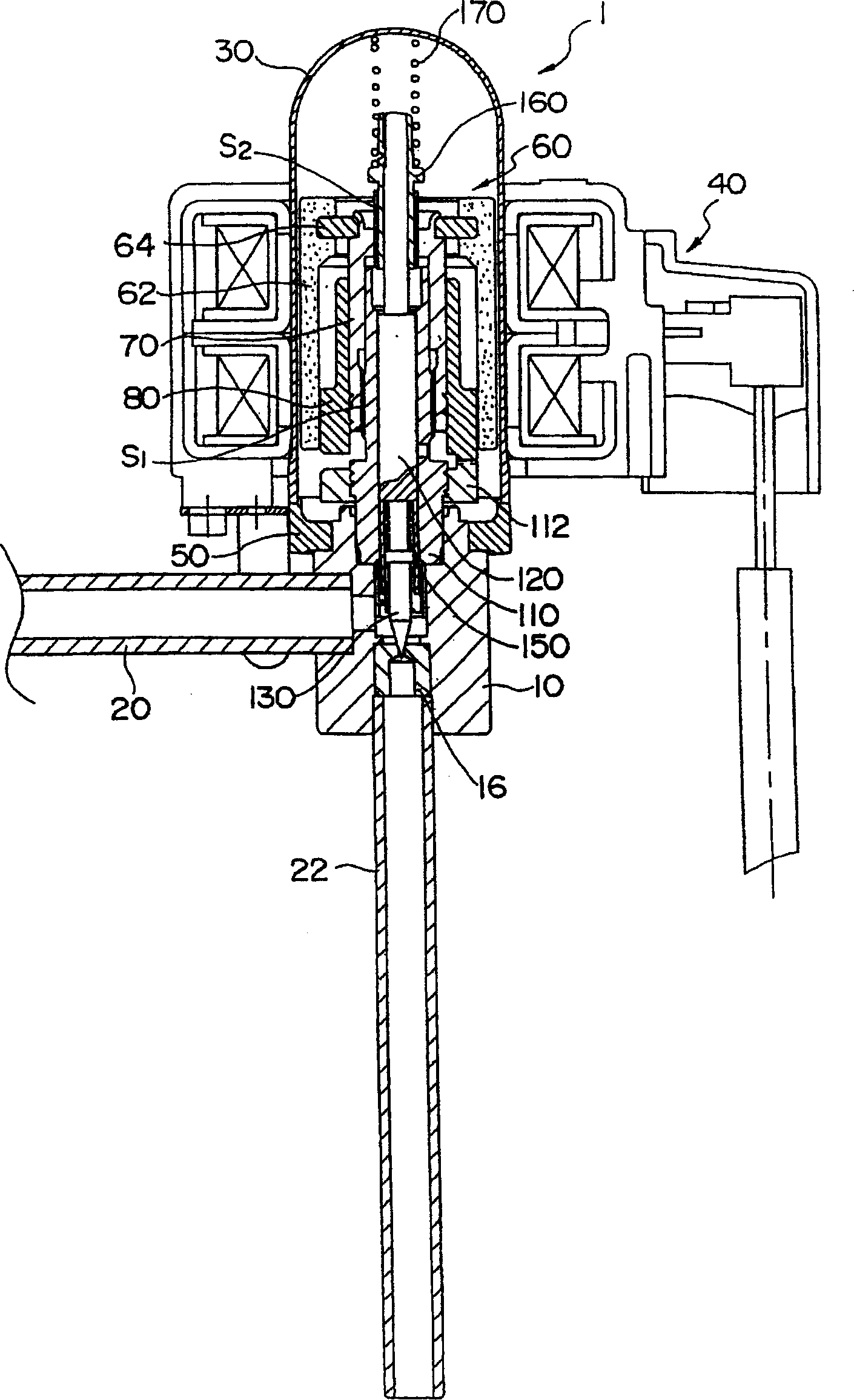
[0021] figure 1 The whole structure of the electric valve of this invention is shown.

[0022] An electric valve denoted as a whole by reference numeral 1 has a valve body 10 , and a valve seat member 16 is inserted into the valve body 10 . Pipes 20 and 22 are connected to the valve body 10 .

[0023] The shell 30 which is a cylindrical pressure vessel is fixed to the upper part of the valve main body 10 via the receiving member 50 . A stator unit 40 of a stepping motor, which is an example of a driving motor, is disposed outside the case 30 .

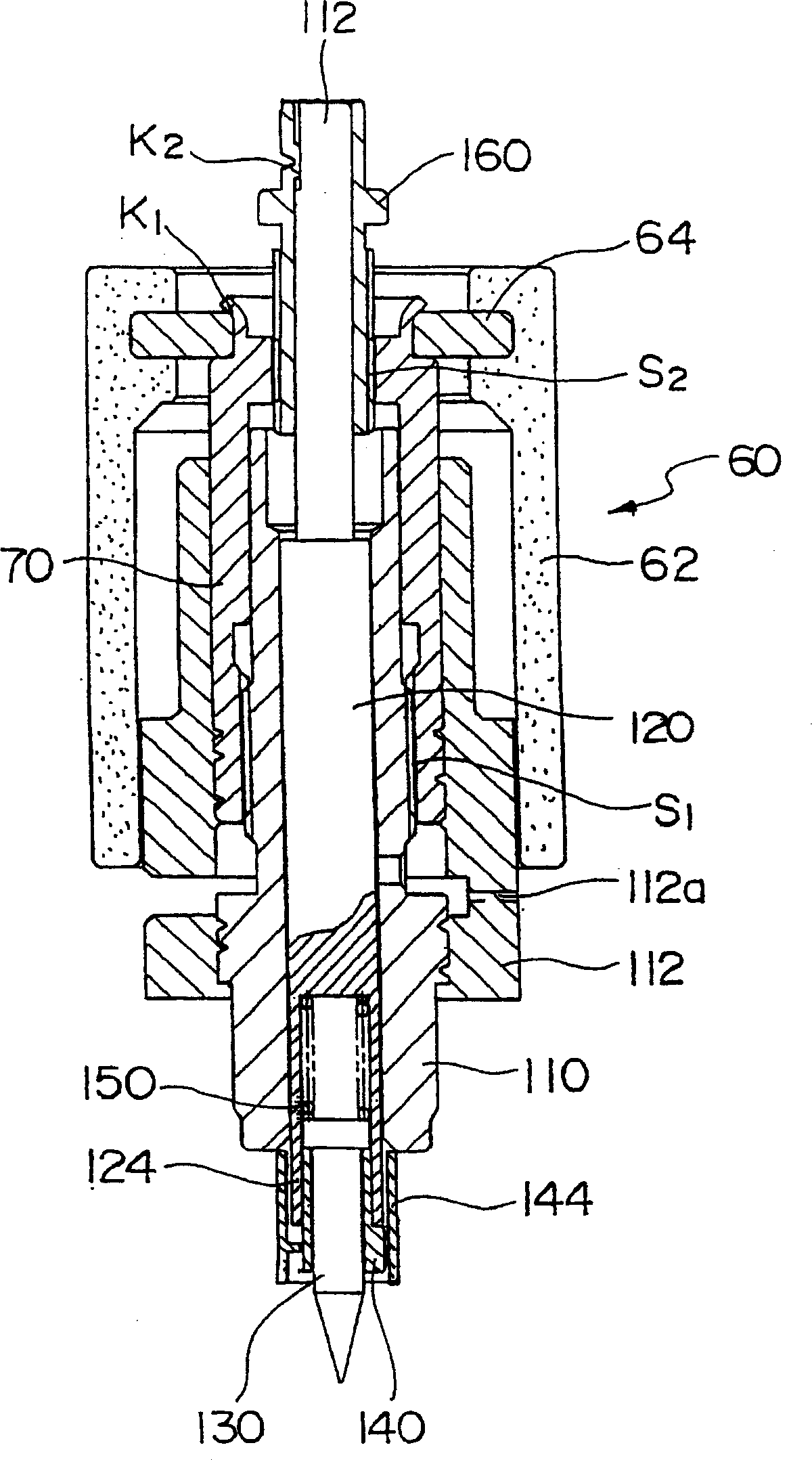
[0024] The rotor unit 60 is rotatably arranged inside the housing 30 . The rotor unit 60 includes a rotor 62 composed of a plastic magnet formed by mixing a magnetic material with resin, and a screw feeding member 70 connected to the rotor 62 through a ring member 64 .

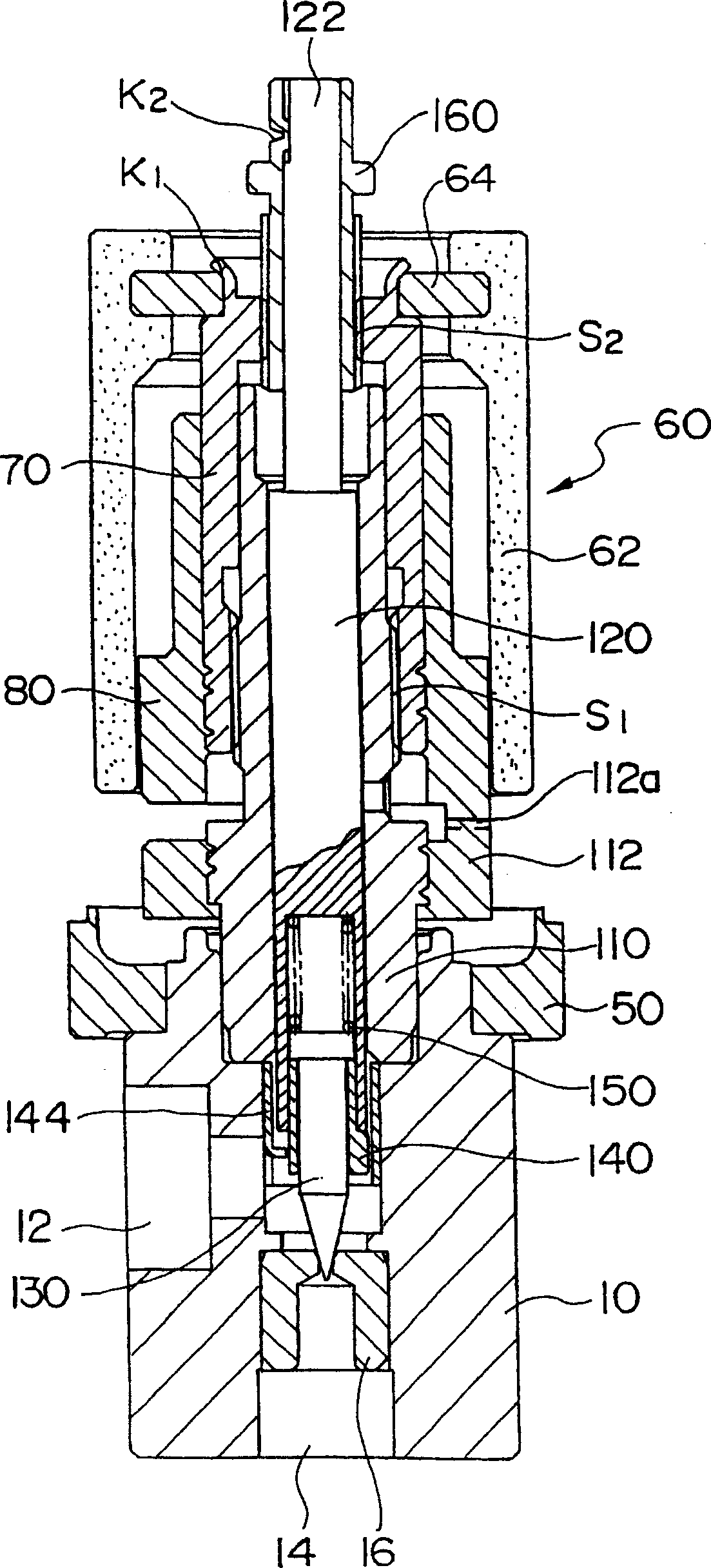
[0025] The screw feeding member 70 has a first threaded portion S1 and a second threaded portion S2 formed in the same direction of rotation, and the pitch of the ...


PUM


Abstract

A motor-operated valve (1) has a rotor unit (60) in a can (30), and is rotationally driven by a stator unit (40). The rotation of the rotor unit (60) is transmitted to a screw feed member (70). A stem member (110) fixed to a valve body (10) is engaged threadedly with the screw feed member (70) by a first screw portion (S1). At the same time, the screw feed member (70) is engaged threadedly with an external thread portion (160) fixed to a valve stem (120) by the second screw portion (S2). The first screw portion (S1) and the second screw portion (S2) constitute a differential screw mechanism, and feeds the valve stem (120) according to a difference in pitch.

Description

technical field [0001] The present invention relates to an electric valve installed and used in an air conditioner, a refrigerator, etc., and relates to an electric valve capable of accurately adjusting the passing flow rate of the refrigerant to a minute amount even when high-pressure refrigerant is used. Background technique [0002] For example, the following patent document 1 represents an existing general electric valve, which has such a mechanism: a rotor arranged on the inside of the casing is rotationally driven by a stator arranged on the outside of the casing, and a screw mechanism is used to convert the rotational motion of the rotor into Linear movement and control of the valve opening of the spool relative to the seat. [0003] Japanese Patent Document 1: JP-A-2001-50415 [0004] In the existing electric valve as mentioned above, the flow rate of refrigerant depends on the effective opening area of ​​the valve port, that is, the ...

Claims


Application Information

Patent Timeline
Patent Type & Authority Applications(China)
IPC IPC(8): F16K1/00F16K31/04F25B41/06
CPCF16K1/04F16K31/04F16K31/506F02M26/54F16K31/06F16K31/00
Inventor 井上靖樋口浩次梅泽仁志
Owner FUJIKOKI MFG CO LTD
Learn More