
Wireless split-type metering device

A split-type, metering technology, applied in signal transmission systems, instruments, electrical signal transmission systems, etc., can solve structural and functional limitations, increase equipment installation, maintenance and management costs, and inconvenient user use, etc., to avoid The effect of data mishandling and shortening the waiting time for inserting a card

Inactive Publication Date: 2006-11-22
大庆英辰创新科技有限公司
View PDF0 Cites 10 Cited by
  • Summary
  • Abstract
  • Description
  • Claims
  • Application Information

AI Technical Summary

Problems solved by technology

[0012] (1) Due to the LED or LCD display window of the electronic meter, and the card slot of the IC card meter, especially the contact IC card meter, it is difficult to be strictly sealed. Conditions are more sensitive;
[0013] (2) Since electricity meters including IC card meters are usually placed in public spaces such as corridors, they are easily accessed by the outside world, and electricity theft such as bypass and grounding and other malicious attacks and damages occur, including charging into the IC card port. Dozens of methods of attack and sabotage, such as pouring water, inserting iron sheets, and shocking with high-voltage igniters, and it is difficult for the management to catch these attackers and saboteurs
In addition to the use of inlet bushings and meter boxes, there is currently no other better protection
On the one hand, these man-made attacks and sabotages have caused a large cost leakage, and on the other hand, they have also significantly increased the cost of equipment installation, maintenance and management
[0014] (3) The current common electronic meters usually use LED digital or LCD liquid crystal display, LED display relatively high power consumption and insufficient information, and LCD display has problems in low temperature and brightness
Although LCD display is a development direction, in cold regions, the use of LCD with good low temperature characteristics will undoubtedly increase the cost of the meter, and LCD display requires better ambient brightness, and the use of LCD with backlight will also significantly increase the metering cost. table cost
[0015] (4) The current various mechanical or electronic meters are limited by their structures and functions. No matter how they are improved in appearance design, it is still difficult to be as beautiful as home appliances, so people often hope to place them in an inconspicuous corner. Or simply wrap them inside the cabinet
[0016] (5) The current IC card meter is usually placed outdoors or in other corners, requiring users to consciously pay attention to the display and alarm information of the meter and recharge in time, otherwise it is easy to automatically cut off the supply of water, electricity, gas and heat. Bring inconvenience to users' daily life
[0017] (6) Even though the current IC card meter can use a user IC card to realize the payment of water, electricity, gas and heat meters at the technical level, each meter itself is still independent, and there is no software and hardware resources that can be shared On the one hand, it brings waste of investment, on the other hand, it is not convenient for users to use

Method used


Image

  • Wireless split-type metering device
  • Wireless split-type metering device

Examples


Embodiment 1

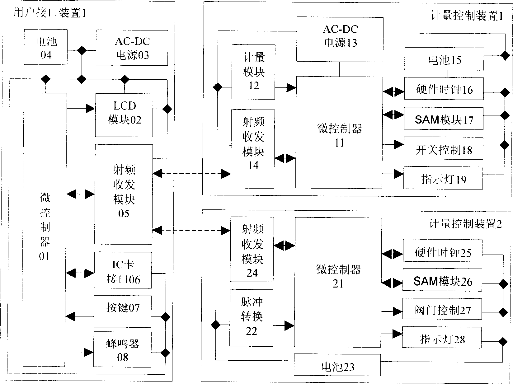
[0052] Such as figure 1Shown is a circuit structure diagram of a split-type multi-rate IC card multi-meter meter device for one household, which includes a user interface device 1, a metering control device 1 for electricity metering, and a metering control device 2 for water metering. There may be only one metering control device in a specific application, or there may be more metering control devices including gas and heat metering.

[0053] (1) User interface device

[0054] The basic function of the user interface device is to display the metering information received from the metering control device through wireless communication. Constitute the necessary basic functional units of the user interface device 1; the additional functions of the user interface device 1 provide IC card payment, function switching and alarm prompt functions, and the user interface device 1 is composed of the IC card interface 06, buttons 07 and buzzer 08 optional additional functional units. ...

Embodiment 2

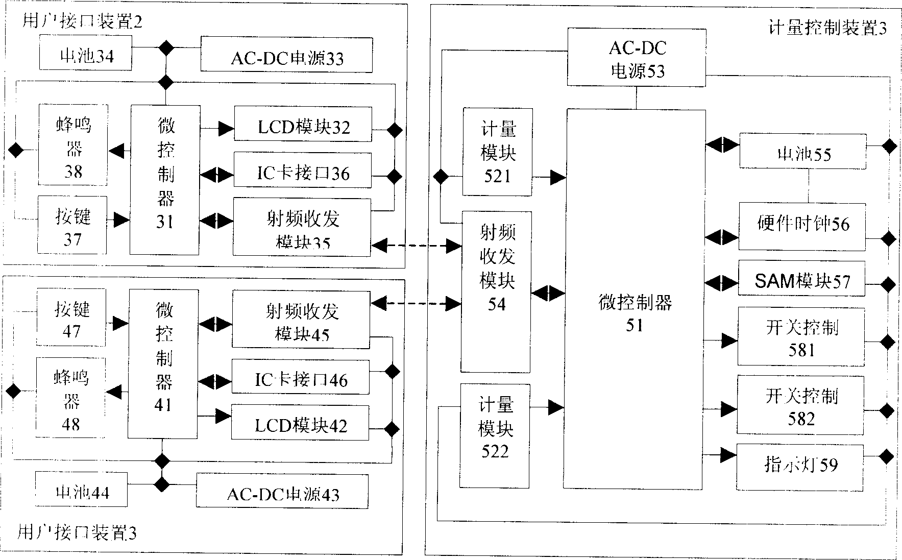
[0069] Such as figure 2 Shown is a circuit structure diagram of a split-type multi-rate IC card multi-meter meter device. For the convenience of description, this embodiment provides the user interface device 2 and the user interface device 3 respectively and the supporting application of the metering control device 3. Condition. There may be one, two or more user interface devices in practical applications, and correspondingly there are the same number of metering and control functional units in the metering control device 3 . In practical applications, there are generally only multi-user meters for electricity metering. For special applications, such as rural power users, using multi-user metering control devices can further reduce costs.

[0070] (1) User interface device

[0071] The user interface device 2 of the present embodiment constitutes the necessary basic functional units of the user interface device 2 by a microcontroller 31, an LCD module 32, an AC-DC power s...


PUM


Abstract

The disclosed wireless split meter comprises: a micro-controller, a meter module, an AC-DC power, a RF transmitting-receiving module, a cell, a hardware clock, a SAM module, and an indicator lamp; wherein, the former four items are necessary; or, forming a user interface device by a micro-controller, a LCD module, an AC-DC power,, a cell, a RF transmitting-receiving module, an IC interface, the press-key, and buzzer for common interface device with the former five items necessary. Wherein, it is fit to use a short-distance dual wireless communication between the calculation control device and user interface.

Description

technical field [0001] The invention belongs to the field of metering instruments and their applications, and in particular relates to a wireless split meter device, including ordinary electromechanical or fully electronic water, electricity, gas and heat meters and IC meters with single or multiple rates. Card (prepaid or controlled postpaid) for water, electricity, gas and heat meters. Its feature is that the function of the meter is divided into two parts: the "metering control device" with safety protection requirements and the "user interface device" without safety protection requirements. Science Medicine) frequency band RF Transceiver (RF Transceiver) module for short-distance two-way data communication. Background technique [0002] Water meters, electric meters, gas meters and heat meters (hereinafter collectively referred to as meters) are commonly used measuring instruments in people's daily life. The traditional water, electricity, and gas meter is a mechanical...

Claims


Application Information

Patent Timeline
IPC IPC(8): G08C17/02G08C19/00
Inventor 王耀邢小云
Owner 大庆英辰创新科技有限公司
Learn More