Electromagnetic pump driving method
A driving method, electromagnetic pump technology, applied in the direction of AC motor control, pump, pump control, etc., can solve the problem of a little delay in closing, and achieve the effect of alleviating the phenomenon of water hammer, reducing backflow, and reducing noise or vibration
- Summary
- Abstract
- Description
- Claims
- Application Information
AI Technical Summary
Problems solved by technology
Method used
Image

Examples
Embodiment 1
[0047] Below, refer to Figure 1 to Figure 4 , to describe an ideal embodiment of the driving method of the electromagnetic pump adopted in order to improve the above-mentioned problems associated with the opening and closing of the valve. Figure 1 to Figure 4 Shown are voltage waveforms applied across the respective solenoid coils 50a and 50b. In addition, the drive voltage (pulse voltage) for each electromagnetic coil 50a and 50b is generated by a drive control circuit not shown, for example, a DC pulse voltage may be generated from a DC power supply voltage, or may be generated by rectifying an AC power supply voltage. DC pulse voltage.
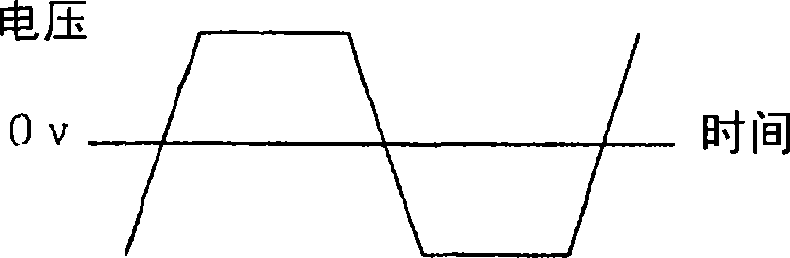
[0048] figure 1 It is shown that the pulse voltage applied for driving the electromagnetic coils 50a and 50b is alternately applied on the positive side and the negative side, and the voltage change when the polarity of the pulse voltage is reversed has at least a gradient linearly connected between the positive side and the negative s...
Embodiment 2
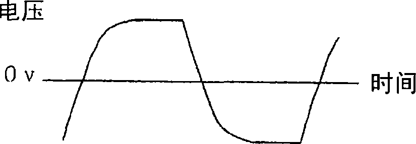
[0051] Below, refer to Figure 5 and Figure 6 Another example of the driving method of the electromagnetic pump will be described. Figure 5 and Figure 6 Shown are voltage waveforms applied across the respective electromagnetic coils 50a and 50b or current waveforms flowing through the respective electromagnetic coils 50a and 50b. Figure 5Shown is a sinusoidal pulse voltage applied for driving the electromagnetic coils 50a and 50b. By applying a sinusoidal pulse voltage, the voltage change when the polarity is reversed is moderated, the moving speed of the movable body 10 is not fast, and the sudden pressure fluctuation of the pump chambers 30a and 30b can be reduced. By doing this, it is possible to reduce the vibration of the cylinder wall surface caused by the sudden change of the force acting on the inner surface of the pump chamber, and the vibration of the stator caused by the sudden change of the electromagnetic force acting on the electromagnetic coils 50a and 50...
Embodiment 3
[0058] Below, refer to Figure 7 to Figure 9 , to describe another example of the driving method of the electromagnetic pump. Figure 7 to Figure 9 Shown are voltage waveforms applied across the respective electromagnetic coils 50a and 50b or current waveforms flowing through the respective electromagnetic coils 50a and 50b.
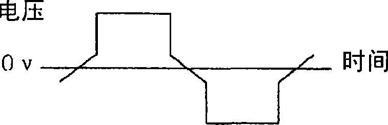
[0059] Figure 7 and Figure 8 It shows that a pulse voltage or a pulse current is applied, and there is a period in which the voltage or current value is zero when the polarity of the driving voltage or the energizing current of each electromagnetic coil 50 a and 50 b is reversed. Figure 8 A linearly continuous slope portion is provided for the voltage current change before and after zero voltage or zero current. In this way, the speed at which the valve is opened and closed can be slowed down, backflow can be reduced, water hammer can be alleviated, and generation of noise or vibration can be reduced. For example, using Figure 7 The driving meth...
PUM
 Abstract
Description
Claims
Application Information