Method for the catastrophic transfer of a thin layer after co-implantation

A transfer method and thin-layer technology, applied in electrical components, microstructure technology, semiconductor/solid-state device manufacturing, etc., can solve problems such as no derivation, and achieve the effect of avoiding ring defects, improving topology, and avoiding damage

Active Publication Date: 2006-11-22
SOITEC SA +1
View PDF8 Cites 2 Cited by
  • Summary
  • Abstract
  • Description
  • Claims
  • Application Information

AI Technical Summary

Problems solved by technology

But the article does not draw practical conclusions from it about the way to obtain high-quality thin layers at moderate cost, especially from the point of view of surface condition

Method used


Image

  • Method for the catastrophic transfer of a thin layer after co-implantation
  • Method for the catastrophic transfer of a thin layer after co-implantation
  • Method for the catastrophic transfer of a thin layer after co-implantation

Examples


example

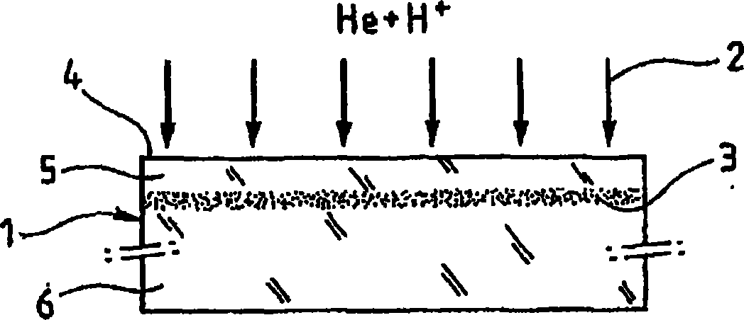
[0100] Joint injection

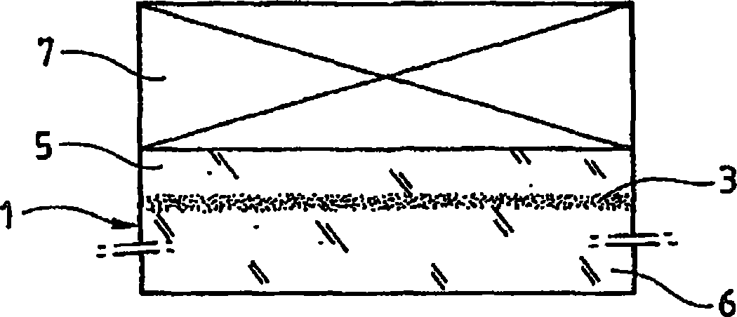
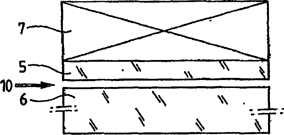
[0101] According to a first embodiment of the present invention, one contains a thermal SiO on the surface (for example, 145nm) 2 The layer of Si substrate (-700μm) can be at 70KeV-10 16 He / cm 2 Helium atoms were injected under the injection conditions of 30KeV-4.25×10 16 H / cm 2 Hydrogen atoms are injected under the same injection conditions. This achieves that the deepest contour line is injected first. The source substrate can then be bonded to a target Si substrate (-700 μm) by molecular bonding. Then, this structure is subjected to heat treatment at about 350°C for a certain period of time (for example, 2 hours). If the heat treatment is adjusted, as disclosed in, for example, European Patent Application 02-293049, the window for obtaining the self-sustained fracture phenomenon is about several hours (ie, the brittle annealing between 2 and 6 hours). Then, as soon as a blade is inserted between the bonding interfaces in the form of impact, the self-sus...


PUM


Abstract

The invention relates to a thin-layer self-sustaining transfer method, according to which - ions of at least one species are implanted in a source substrate at a given depth relative to a surface of the source substrate at a certain dose, - bringing a stiffener into intimate contact with the source substrate, - applying heat treatment to the source substrate at a given temperature for a given time to create a weakened buried region substantially at a given depth, and without inducing thermal detachment of the thin layer, - applying a controlled pulse of energy to the source substrate in a temporally localized manner so as to induce The rest of the self-sustaining detachment.

Description

Technical field [0001] The present invention relates to a transfer method of an ultra-thin layer (also known as a thin layer) that uses the fracture self-sustaining expansion induced by impact energy. It is especially used in the fields of microelectronics, micromechanics, optics, and integrated electronics. Background technique [0002] As is known, the separation of the thin layer can be achieved by injecting chemicals into the source substrate (for example, made of silicon) to promote the formation of a defect region at a certain depth. These defects may be some tiny bubbles and / or small disks and / or tiny cavities and / or misplaced rings and / or other crystal defects, which locally disturb the crystal quality of the material; its characteristics, density, and size are greatly Depends on the species being injected (typically hydrogen injected) and the characteristics of the source substrate. A heat treatment can then be applied to allow the development of specific defects present...

Claims


Application Information

Patent Timeline
Patent Type & Authority Applications(China)
IPC IPC(8): H01L21/762B81C99/00
CPCH01L21/76254H01L21/265H01L21/762H01L21/30H01L21/46
Inventor 纳古耶特-丰·纳古耶伊恩·凯莱弗科克里斯泰勒·拉加赫-布兰查德康斯坦丁·鲍尔戴勒奥莱利·陶泽恩弗兰克·弗奈尔
Owner SOITEC SA
Why Eureka
Try Eureka