
RF transmission method, mri apparatus, and auxiliary coil

A technology of transmitting coil and auxiliary coil, applied in the field of radio frequency transmission, can solve the problem of weak magnetic field strength, etc., and achieve the effect of enhancing magnetic field strength, improving transmission efficiency and reducing power

Inactive Publication Date: 2006-11-29
GE MEDICAL SYST GLOBAL TECH CO LLC
View PDF2 Cites 4 Cited by
  • Summary
  • Abstract
  • Description
  • Claims
  • Application Information

AI Technical Summary

Problems solved by technology

[0006] However, if there is a distance between the transmit coil and the subject, the magnetic field strength applied to the subject will be so weak that a significant amount of power is required to transmit RF pulses from the body coil to excite the subject

Method used


Image

  • RF transmission method, mri apparatus, and auxiliary coil
  • RF transmission method, mri apparatus, and auxiliary coil
  • RF transmission method, mri apparatus, and auxiliary coil

Examples


no. 1 example

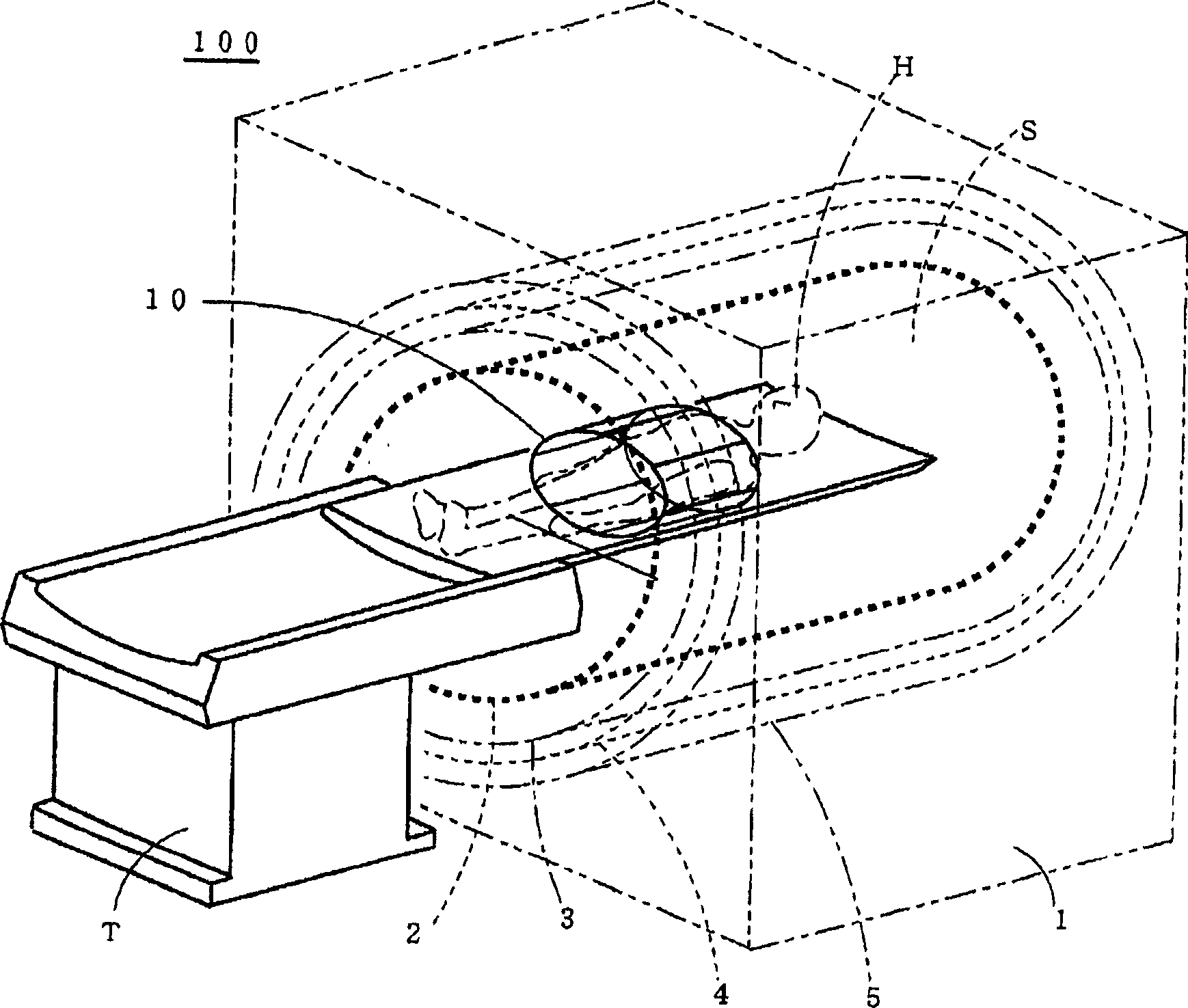
[0041] figure 1 is a perspective view showing the MRI apparatus 100 and the auxiliary coil 10 according to the first embodiment.

[0042] In the MRI apparatus 100 , the magnet device 1 is formed with a cavity (cylindrical space) S into which a subject H lying on a cradle of a table T is inserted. In this magnet device 1 , a body coil 2 , an RF shield 3 and a gradient coil 4 are concentrically arranged in this order from the side of the cavity S of the magnet device to the outside thereof. The main magnetic field generating magnet 5 is provided outside the gradient coil 4 .

[0043] The auxiliary coil 10 is a birdcage coil, and is worn by the subject H.

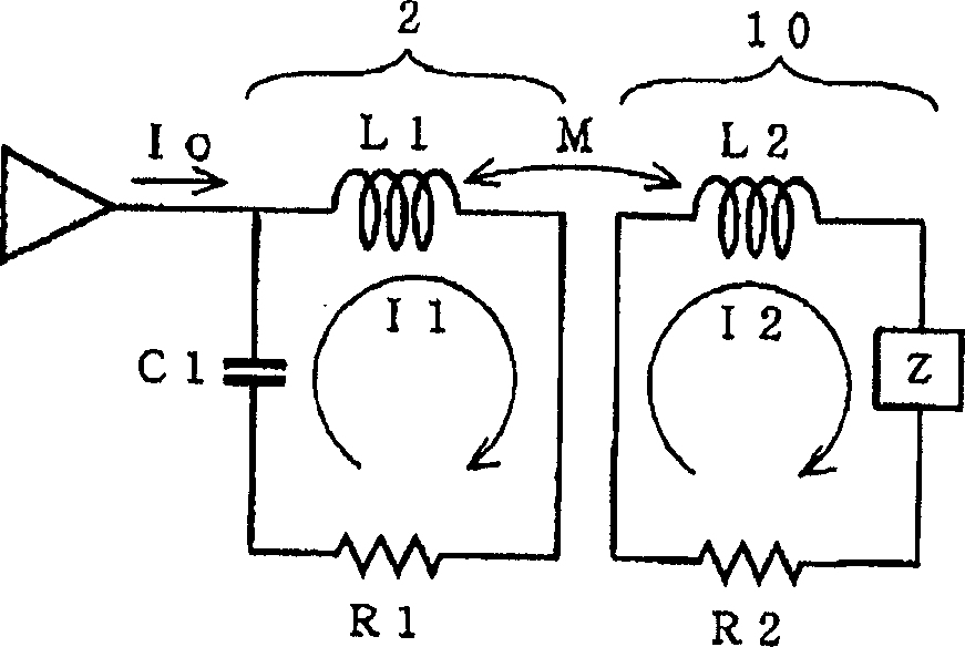
[0044] figure 2 Equivalent circuits of the body coil 2 and the auxiliary coil 10 are shown respectively.

[0045] The body coil 2 is of resonance type and includes an inductor L1, a capacitor C and a resistor R1.

[0046] The auxiliary coil 10 includes an inductance L2, an impedance Z and a resistance R2.

[0047] The bod...


PUM


Abstract

The present invention seeks to intensify the strength of a magnetic field to be applied to a subject. An auxiliary coil is interposed between a body coil incorporated in a magnet assembly included in an MRI apparatus and the subject. When RF pulses are transmitted from the body coil, an induced current flows through the auxiliary coil and generates a magnetic field. The magnetic field excites the subject near the subject.

Description

technical field [0001] The present invention relates to radio frequency (RF) transmission methods, magnetic resonance imaging (MRI) equipment and auxiliary coils. More particularly, the present invention relates to an RF transmission method, an MRI apparatus, and an auxiliary coil capable of enhancing the strength of a magnetic field applied to a subject. Background technique [0002] In a magnet device included in a typical MRI apparatus, body coils, RF shields, gradient coils, and main magnetic field generating magnets are arranged in this order from the bore side to the outside of the magnet device (see, for example, the patent document 1 and 2), wherein the cavity is an imaging space. [0003] [Patent Document 1] Japanese Unexamined Patent Publication 2000-116619 [0004] [Patent Document 2] Japanese Unexamined Patent Publication 2004-248928 [0005] The cavity, which is the imaging space in the MRI apparatus, has a large inner diameter enough to accommodate a very la...

Claims


Application Information

Patent Timeline
Patent Type & Authority Applications(China)
IPC IPC(8): A61B5/055G01R33/32G01R33/36
CPCG01R33/34046G01R33/3642
Inventor 贯原谦一石黑孝至
Owner GE MEDICAL SYST GLOBAL TECH CO LLC
Learn More