Light element and preparation method, and its backlight mould set

A technology of light guide element and backlight module, applied in the direction of optical element, diffuser element, light guide, etc., can solve the problems of light energy loss, boundary glow line and dark line generation, increase assembly time and cost, etc., to increase mechanical strength. , The effect of improving optical defects and reducing light energy loss

Inactive Publication Date: 2006-11-29
HONG FU JIN PRECISION IND (SHENZHEN) CO LTD +1
View PDF0 Cites 14 Cited by
  • Summary
  • Abstract
  • Description
  • Claims
  • Application Information

AI Technical Summary

Problems solved by technology

[0005] (1) Lamination design of reflective sheet: Paste a high-reflective patch on the joint between the light guide plate and the frame to reduce the loss of light energy, but often because the reflected light energy is not easy to control, there are still bright lines and dark lines on the boundary produce
In addition, the frame can also be made of highly reflective plastic material, which can also achieve the effect of reducing the loss of light energy, but it also produces bright and dark lines at the border
[0006] (2) Optical correction design at the edge of the light guide plate near the frame: mainly to increase or decrease the optical dot density at the edge of the reflective surface of the light guide plate to improve the optical problems of bright lines and dark lines at the boundary, but the assembly gap is often still Can cause optical and visual asymmetry
Or paste a low-reflection optical film on the edge of the exit surface of the light guide plate close to the frame for light reduction and shading, but this design will increase the assembly time and cost
[0007] (3) Diffusion sheet design: print patterns on the diffusion sheet to reduce the contrast between the brightness of the frame and the light guide plate. However, this design still has the disadvantage of light energy loss and increases the material cost of the backlight module.
[0008] To sum up, the existing backlight modules still cannot economically and effectively reduce optical defects such as bright and dark lines on the boundary between the light guide plate and the frame and light energy loss through the above-mentioned several technical means.

Method used


Image

  • Light element and preparation method, and its backlight mould set
  • Light element and preparation method, and its backlight mould set
  • Light element and preparation method, and its backlight mould set

Examples


Embodiment Construction

[0035] The light guide element and the backlight module using the light guide element of the present invention will be further described in detail below with reference to the drawings and multiple embodiments.

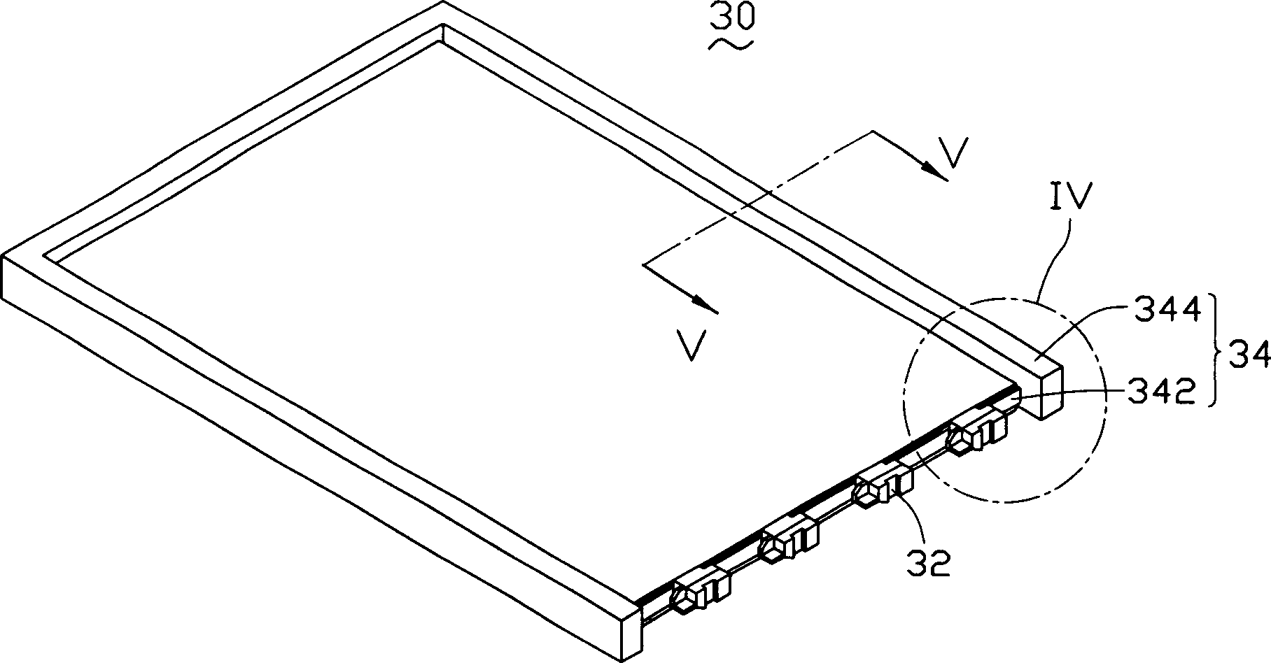
[0036] Please refer to image 3 , Figure 4 and Figure 5 The first embodiment of the present invention provides a light guide element 34, which includes a light guide plate 342, and the light guide plate 342 includes an incident surface 3422, an exit surface 3424 connected to the incident surface 3422, and an exit surface 3424 opposite to the exit surface 3424. The corresponding reflective surface (not shown in the figure), and the three sides 3426 except the incident surface 3422 ; and a frame 344 , the frame 344 is integrated with the three sides 3426 of the light guide plate.

[0037] Wherein, in this embodiment, the light guide plate 342 is made of transparent polycarbonate, and the frame 344 is made of white polycarbonate with high reflection coefficient. The ...


PUM


Abstract

The invention relates to a light guide component and the preparing method thereof as well as a backlight module using it. And it comprises a light guide plate and a frame, where the light guide plate comprises an incident face, an outgoing face connected with the incident face, a reflecting face corresponding to the outgoing surface and three side faces beside the incident face, and the frame is integrated with the above three sides. And it is formed by double-color injection moulding technique, able to eliminate gap between light guide plate and frame, and thus reducing light energy losses and improving its boundary optical phenomenon. And the invention also provides a background module using it, which has advantages of low material costs, high assembling speed and high mechanical intensity.

Description

【Technical field】 [0001] The invention relates to a light guide element, its preparation method, and its backlight module. 【Background technique】 [0002] Liquid crystal displays with side-lighting backlight modules are widely used in fields such as notebook computers, vehicle displays, and mobile phones due to their small size, light weight, and uniform brightness. The backlight module is an optical mechanism that can convert scattered point light sources or line light sources into uniform planar light sources. Since the liquid crystal display is a non-luminous display device, a backlight module is required to produce a display function. The performance of the backlight module often directly affects the image quality of the liquid crystal display. Therefore, the backlight module becomes the most important component in the liquid crystal display. [0003] Such as figure 1 and figure 2 As shown, the backlight module 1 in the prior art includes a light guide plate 10, sev...

Claims


Application Information

Patent Timeline
Patent Type & Authority Applications(China)
IPC IPC(8): G02B5/02G02F1/1335
CPCG02B6/0088G02B6/0065G02B6/0035G02B6/0081
Inventor 许铭富
Owner HONG FU JIN PRECISION IND (SHENZHEN) CO LTD
Why Eureka
Try Eureka