

Small DC motor
A technology of DC motors and motor frames, applied in the direction of electric components, DC commutators, electrical components, etc., can solve the problems of large magnet thickness and achieve the effect of maintaining magnetism
- Summary
- Abstract
- Description
- Claims
- Application Information
AI Technical Summary
Problems solved by technology
Method used
Image

Examples
Embodiment 1
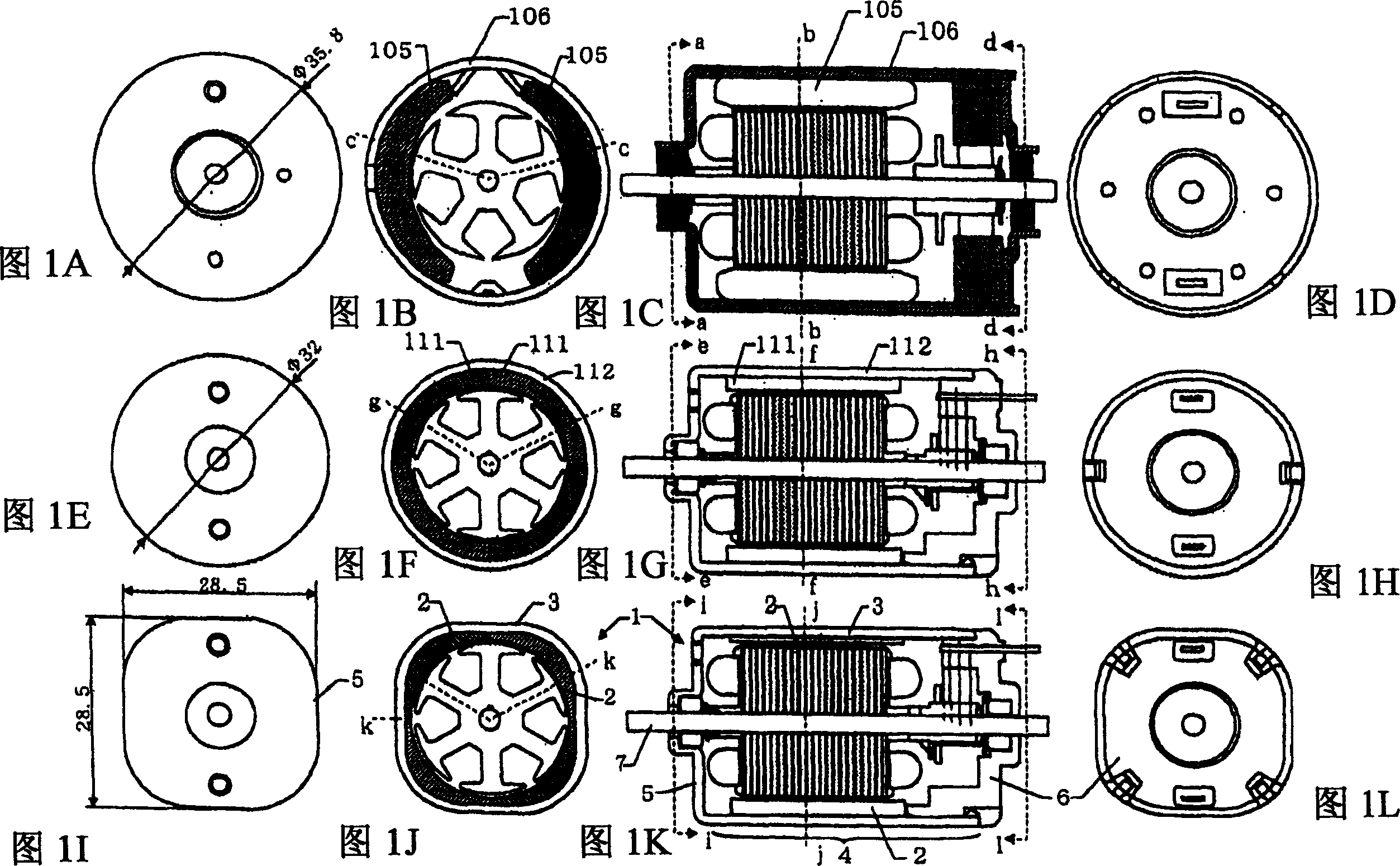
[0041] 1A to 1L show explanatory diagrams illustrating the features of the small-sized DC motor of the present invention while comparing with existing similar products.
[0042] 1A to 1D are diagrams showing the structure of a conventional general-purpose DC motor utilizing a ferrite magnet, wherein FIG. 1A is a diagram of one side when viewed in a direction indicated by an arrow a in FIG. 1C , and FIG. 1B is a transverse sectional view along line b-b in FIG. 1C , FIG. 1C is a sectional view along line c-c in FIG. 1B , and FIG. 1D is the other side when viewed in the direction indicated by arrow d in FIG. 1C diagram of .
[0043] In FIGS. 1A to 1D, a structure is employed in which two magnets 105 magnetized into N poles and S poles in the direction of rotation and each having an arcuate section are arranged along the length of a cylindrical motor frame 106. The side walls are arranged in axisymmetric manner, and a gap is arranged between the two magnets 105 .
[0044] In thi...
Embodiment 2
[0089] Next, the magnet and motor frame of the present invention will be described by comparing with the magnet and motor frame in the conventional example.
[0090] Figures 3A1 to 3E1 with Figures 3A2 to 3E2 Illustrative diagrams describing various embodiments of the invention are shown. Note that in Figures 3A1 to 3E1 with Figures 3A2 to 3E2 In , the figures with figure numbers suffixed with "1" are figures showing the end plates of the motor frame. In other words, they are diagrams showing the respective external shapes of the motor frame. The diagrams with figure numbers suffixed with "2" are diagrams showing respective sections of the motor frame.
[0091] exist Figure 3A1 with 3A2 Among them, when viewed in section, the motor frame 3a adopts a substantially circular shape, and the magnet 2a is formed in such a shape that secures the magnetic permeability of the magnet necessary for maintaining the performance of the motor, which suppresses the change of the m...
Embodiment 3
[0099] Figure 6A with 6B A cross-sectional view of a coreless motor to which the magnet structure of the present invention is applied is shown.
[0100] Figure 6A is along Figure 6B The profile of line n-n in , and Figure 6B is along Figure 6A Transversal profile of line m-m in . The small DC motor of the present invention includes the coreless motor 29 of the present invention.
[0101] The coreless motor 29 comprises an armature rotatably mounted in a motor frame 30 comprising a commutator die 37 , an armature winding forming element 38 and a shaft 7 .
[0102] The motor frame 30 of the coreless motor 29 includes a cylindrical portion 31 , an end plate portion 32 provided continuously with the cylindrical portion 31 , and a bearing housing portion 33 provided continuously with the end plate portion 32 . Inside the bearing seat portion 33 , the shaft 7 is rotatably supported by two bearings 34 , 35 separated from each other so as to be provided at upper and lower ...
PUM
 Abstract
Description
Claims
Application Information