Ring type heat exchanging system

A heat exchange device and loop technology, applied in indirect heat exchangers, lighting and heating equipment, cooling/ventilation/heating transformation, etc., can solve problems such as low yield rate of finished products, unfavorable return of working liquid, and obstruction of liquid return

Inactive Publication Date: 2006-12-06
FU ZHUN PRECISION IND SHENZHEN +1
View PDF0 Cites 25 Cited by
  • Summary
  • Abstract
  • Description
  • Claims
  • Application Information

AI Technical Summary

Problems solved by technology

[0004] (1) The steam and the return liquid flow in the same pipe in the opposite direction (counter-current flow), which hinders the return of the liquid by capillary force, and then dries out (dry-out), resulting in a rapid temperature rise and limiting its maximum heat dissipation capacity
[0005] (2) The condensed liquid return channel in the condensation section uses the same capillary structure as the evaporation section. Although the capillary force increases as the pore diameter decreases, the frictional resistance of the fluid also increases, which is not conducive to the return of the working liquid. It is easy to dry out, which limits its maximum heat dissipation capacity
[0007] (1) The porous capillary structure in the evaporation part 1 is made of sintered metal powder, so the internal pore size usually cannot obtain uniform structural characteristics and quality, not only cannot effectively guide the working fluid to produce the same level of liquid, Vapor two-phase change, and because the thickness of the capillary structure is difficult to control, the yield of finished products is low, the processing is difficult and the cost is high, it is not conducive to mass production
[0008] (2) The evaporating part 1 and the condensing part 4 are designed in a cylindrical shape, which cannot make good thermal contact with the heating element or heat dissipation element in a flat shape, which reduces the heat transfer efficiency, and is not conducive to the trend of light and thin design of the product. In terms of application and promotion has its limitations
[0011] (5) The evaporation part 1 lacks the design of the steam chamber, which cannot accommodate the pressure of the saturated steam generated by the working fluid after absorbing heat, so the temperature tends to rise rapidly and the heat dissipation effect becomes poor
[0012] (6) In addition to the unfavorable factors of increasing the overall thermal resistance due to the increase of the interface thermal resistance and the spreading resistance, the heat dissipation method of the condensing part 4 is provided by the limited peripheral area of ​​the fluid transmission conduit, It is also not conducive to the effective transfer of heat from the high-enthalpy fluid that flows rapidly through the conduit, severely limiting its maximum heat dissipation capacity
[0013] (7) Although it may be acceptable for heat dissipation applications in certain fields that can only handle heat dissipation in a specific power range, it cannot solve heat dissipation products in a very low power range; however, the existing loop heat pipe is used for heat dissipation of CPU Generally speaking, the standby state (idle) after full power is turned on usually only consumes very low power, so that only a small amount of steam can be generated in the evaporation part 1, which will gradually push the working fluid to the circuit space but cannot be used. Sufficient condensate flows back to the evaporator 1, eventually causing drying and heating, which is an activation problem that is not easy to eliminate in the prior art

Method used


Image

  • Ring type heat exchanging system
  • Ring type heat exchanging system
  • Ring type heat exchanging system

Examples


Embodiment Construction

[0035] The present invention will be further described below in conjunction with the embodiments with reference to the accompanying drawings.

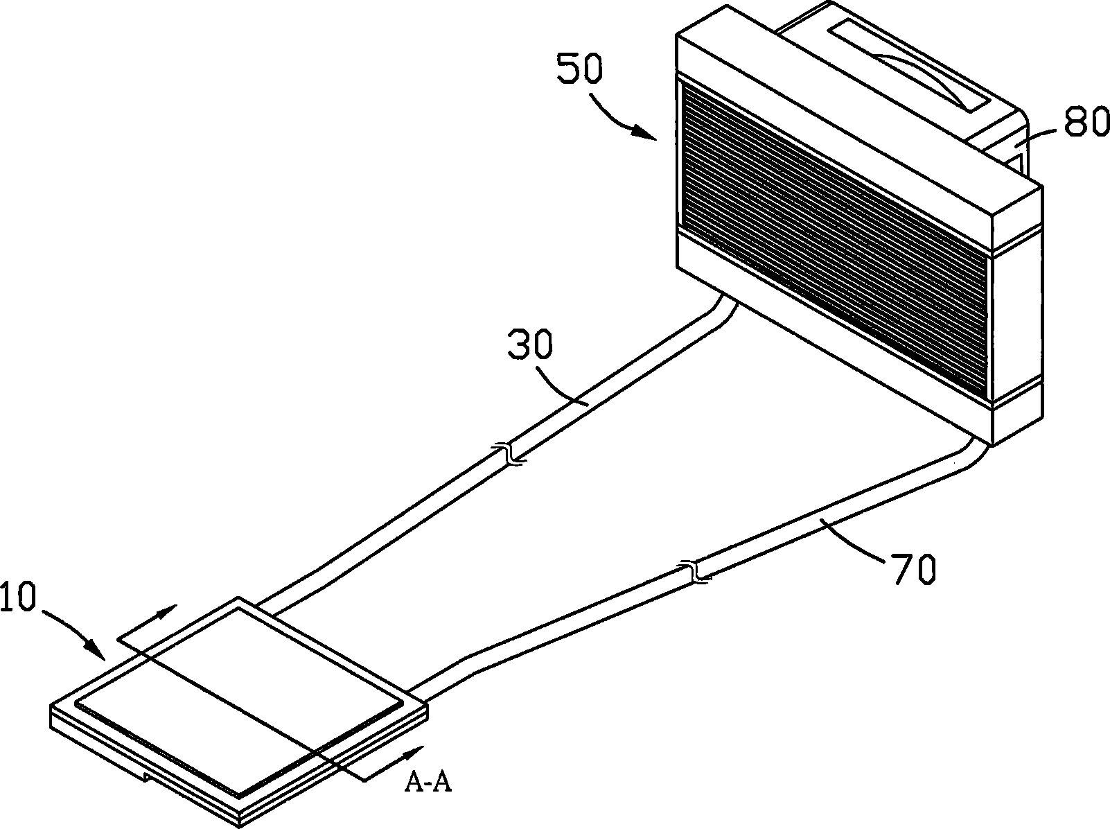
[0036] figure 2 It is a three-dimensional schematic diagram of the appearance of the first embodiment of the loop heat exchange device of the present invention, including an evaporation part 10 , a steam conduit 30 , a condensation part 50 and a return conduit 70 .

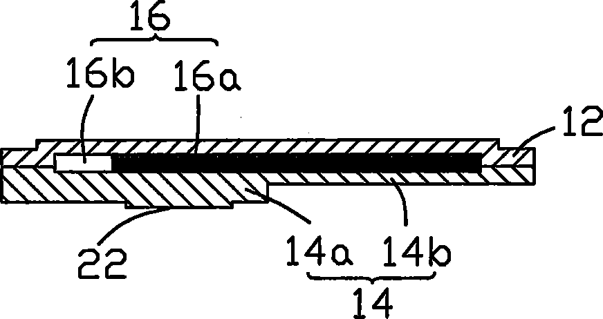
[0037] image 3 for figure 2 The evaporator 10 in the figure is a sectional view viewed along the A-A section, the evaporator 10 includes an upper cover plate 12 and a lower cover plate 14, and the upper cover plate 12 and the lower cover plate 14 form a sealed flat cavity 16, in which There are multiple microfluidic channel capillary structures composed of several layers of tightly arranged metal meshes, and the capillary structure divides the cavity space into a liquid phase microfluidic channel area 16a and a low flow resistance steam channel area 16b. The upper and ...


PUM


Abstract

The present invention provides a ring circuit heat exchange equipment. It includes an evaporation portion, a steam conduit, a condensation portion and a reflux conduit. Said evaporation portion is a closed cavity body its interior is equipped with a multiple microflow channel capillary structure, said capillary structure can separate the cavity body space into liquid phase microflow channel zone and steam channel zone, said two channel zones are series-connected with said condensation portion respectively by means of external steam conduit and reflux conduit so as to form a complete ring circuit type heat exchange radiation system. Said condensation portion is formed from fins and condensation tube. Said invention not only has high heat transfer efficiency, but also can obtain good heat exchange effect.

Description

【Technical field】 [0001] The present invention relates to a heat exchange device, especially a loop heat exchange device that does not need external power and can play an all-round antipyretic function with changes in high and low power output of heating elements. 【Background technique】 [0002] With the rapid development of the electronic information industry, high-tech electronic products are developing toward thinner, lighter, more compact, multi-functional, and high-speed trends. However, as the operating frequency and speed of electronic components continue to increase, the heat released by them will increase. High, which seriously threatens the operation performance and stability of electronic components, and even burns these expensive electronic components due to high temperature. Based on the quality of the cooling device, it will directly affect the life and operation quality of electronic components. In order to ensure the normal operation of electronic components, ...

Claims


Application Information

Patent Timeline
Patent Type & Authority Applications(China)
IPC IPC(8): F28D15/04H05K7/20G06F1/20
CPCF28D15/0266
Inventor 刘泰健童兆年侯春树李志鹏
Owner FU ZHUN PRECISION IND SHENZHEN
Why Eureka
Try Eureka