Method and device for operating drive unit

A technology of drive unit and operating parameters, which is applied in engine control, electric controller, machine/engine, etc., and can solve problems such as unstable vibration characteristics of idling regulators

Inactive Publication Date: 2006-12-13
ROBERT BOSCH GMBH
View PDF0 Cites 0 Cited by
  • Summary
  • Abstract
  • Description
  • Claims
  • Application Information

AI Technical Summary

Problems solved by technology

This can lead to an unstable, oscillatory start-up characteristic of the output of a dead-running regulator with proportional and integral parts superimposed on the output of a first-order differential time element

Method used


Image

  • Method and device for operating drive unit
  • Method and device for operating drive unit
  • Method and device for operating drive unit

Examples


Embodiment Construction

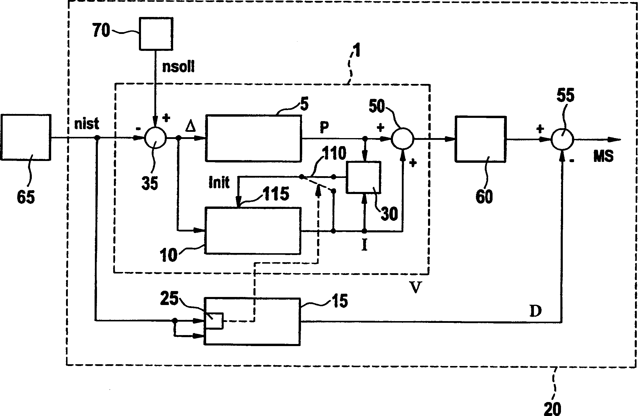
[0018] exist figure 1 Among them, 20 represents the device for operating the drive unit. The drive unit can drive the car, for example, and for this purpose is included in the figure 1 internal combustion engine not shown. The device 20 is here an engine controller, or it can be implemented in software and / or hardware in such an engine controller. When an internal combustion engine is used, it can be, for example, an Ottomotor or a diesel engine. The device 20 includes a controller 1 , which keeps the actual value of an operating variable of the drive unit to follow the setpoint value of this operating variable. In the following it is assumed by way of example that the controller 1 is a speed controller which keeps the actual value nist of the engine speed following the target value nsoll of the engine speed. For this purpose, the rotational speed regulator 1 comprises a proportional regulator or proportional part 5 and an integral regulator or integral part 10 . Time-dis...


PUM


Abstract

The invention relates the method and device for running driver element. The driver element has running parameter and rotation rate accommodator (1). The accommodator comprises the proportional part (5) and partial integration (10). According the outcoming signal of proportional part (5), initialize the partial integration (10).

Description

technical field [0001] The invention is based on a method and a device for operating a drive unit according to the preambles of the independent claims. Background technique [0002] Drive units of motor vehicles are known which comprise an idle speed controller with a proportional part and an integral part. In order to avoid a so-called undercut or extinguishment of the engine after a fuel drop, ie after a quick release of the gas pedal, a first-order differential time element, in particular weighted, is used here. In steady engine operation, however, the first-order differential time element must be switched off in order to avoid instabilities. The combination of a high negative control deviation of the value and the control limit of the freewheel speed controller ensures that the differential time element of the first order is not synchronized with the freewheel controller with proportional and integral parts when the fuel supply drops sharply from high speeds. intervent...

Claims


Application Information

Patent Timeline
Patent Type & Authority Applications(China)
IPC IPC(8): F02D28/00F02D41/02
CPCG05B11/42
Inventor H·瓦纳B·巴卡斯C·蒙茨
Owner ROBERT BOSCH GMBH
Why Eureka
Try Eureka