
Distortion cancellation in a transimpedance amplifier circuit

A technology of transimpedance amplifiers and photodetectors, which is applied in the direction of improving amplifiers to reduce nonlinear distortion, amplifiers, and amplifiers controlled by light, etc. It can solve problems such as increasing noise and distortion, reducing bandwidth, and TIA cannot be packaged together with photodiodes.

Inactive Publication Date: 2006-12-13
EMCORE INC
View PDF4 Cites 6 Cited by
  • Summary
  • Abstract
  • Description
  • Claims
  • Application Information

AI Technical Summary

Problems solved by technology

[0009] However, as mentioned above, the high power dissipation in all of these prior art examples prevents the TIA from being co-packaged with a photodiode in a TO can or other low cost package
Separate packaging of photodiodes and TIAs increases parasitic capacitance, which reduces bandwidth and increases noise and distortion

Method used


Image

  • Distortion cancellation in a transimpedance amplifier circuit
  • Distortion cancellation in a transimpedance amplifier circuit
  • Distortion cancellation in a transimpedance amplifier circuit

Examples


Embodiment Construction

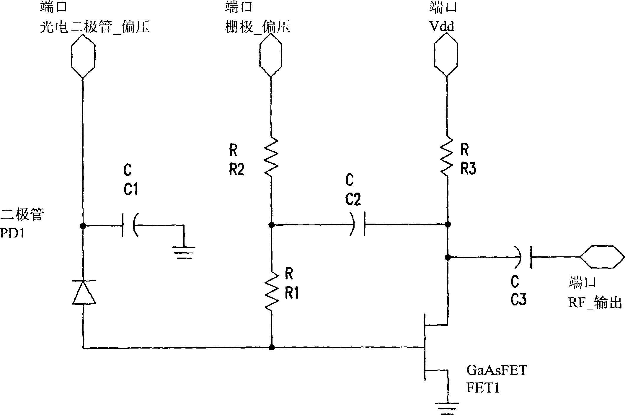
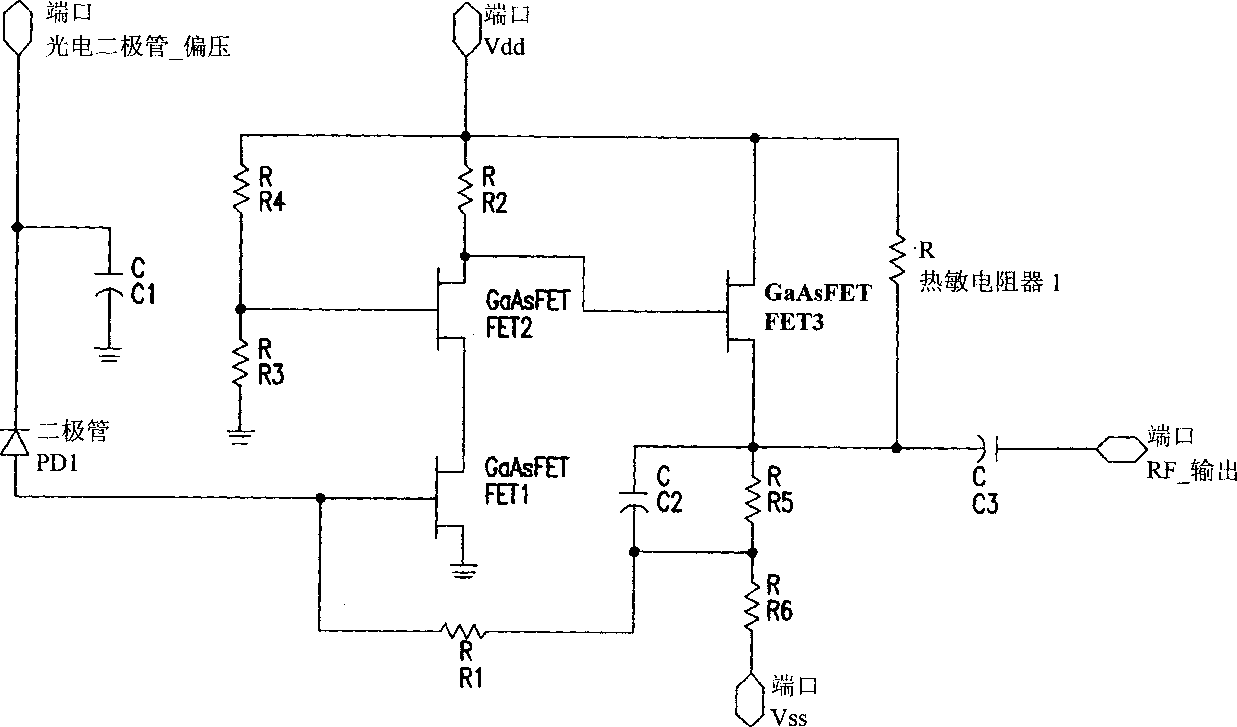
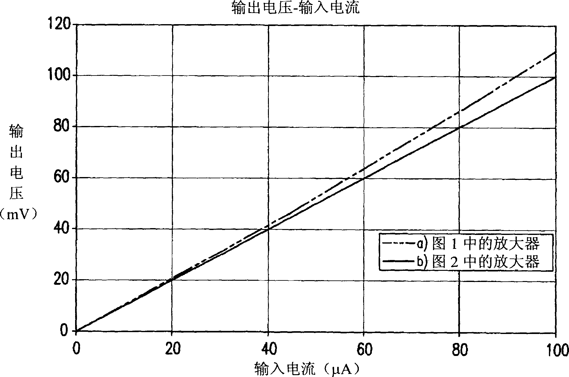
[0028] Details of the invention, including exemplary aspects and embodiments thereof, are set forth below. Referring to the drawings and the following detailed description, like reference numerals are used to designate like or functionally similar elements and are intended to illustrate major features of exemplary embodiments in an extremely simplified illustration. Moreover, the drawings are not intended to depict every feature of actual embodiments nor relative dimensions of the depicted elements, and are not drawn to scale.

[0029] For new fiber-to-the-home (FTTH) applications that include an analog optical CATV receiver at each customer site, there is a strong desire from some network interface hardware manufacturers and service providers (such as telephone or cable operators) to reduce power consumption and reduce hardware costs. To this end, the present invention provides a novel design of a single-ended analog TIA with low enough power consumption to allow TO packagin...


PUM


Abstract

An optical receiver for use in an optical communications system in which an analog signal is transmitted over an optical fiber including a housing with a photodetector (PD1) coupled to the external optical fiber for receiving an optical communications signal; and a transimpedance amplifier (FET1,FET2) coupled to the electrical output of the photodetector (PD1) and having a bias current in a second stage (FET3) set to a predetermined value that minimizes the distortion in the output signal created in a first amplification stage (FET1,FET2) by a cancellation effect.

Description

technical field [0001] The present invention relates to optical receivers, and more particularly to transimpedance amplifiers having a non-linear operating characteristic and used in a photodiode and electronic An interface is provided between network terminal devices. Background technique [0002] Many types of optical communication systems are known in the art, which include an optical transmission section that converts an electrical signal into a modulated light beam that is coupled into an optical fiber, and a receiving section that receives the optical signal from the optical fiber and converts it into an electrical signal . Traditionally, the optical receiver section includes an optical assembly to focus or direct light from an optical fiber onto a photodetector, which in turn is connected to an amplifier / limiter circuit on a circuit board. The photodetector or photodiode is usually housed in a hermetically sealed package to protect it from harsh environmental condit...

Claims


Application Information

Patent Timeline
Patent Type & Authority Applications(China)
IPC IPC(8): H03F1/32H03F3/08H04B10/18H04B10/43
CPCH03F1/3205H03F1/3211H03F1/226H03F3/082H03F1/301H03F1/223H03F3/505H03F3/087
Inventor 布里翁·林恩·卡斯珀伊娃·玛丽亚·佩拉尔
Owner EMCORE INC
Learn More