
Bush for a chuck and method of its manufacture

An intermediate shaft and chuck technology, applied in the direction of chucks, manufacturing tools, couplings, etc., can solve the problem of high cost and achieve the effects of low processing cost, small clamping force loss and high production accuracy

Active Publication Date: 2006-12-13
SCHUNK GMBH & CO KG SPANN UND GREIFTECHN
View PDF1 Cites 8 Cited by
  • Summary
  • Abstract
  • Description
  • Claims
  • Application Information

AI Technical Summary

Problems solved by technology

Such manufacturing methods are costly and associated with long cycle times due to the large number of different production processes required

Method used


Image

  • Bush for a chuck and method of its manufacture
  • Bush for a chuck and method of its manufacture
  • Bush for a chuck and method of its manufacture

Examples


Embodiment Construction

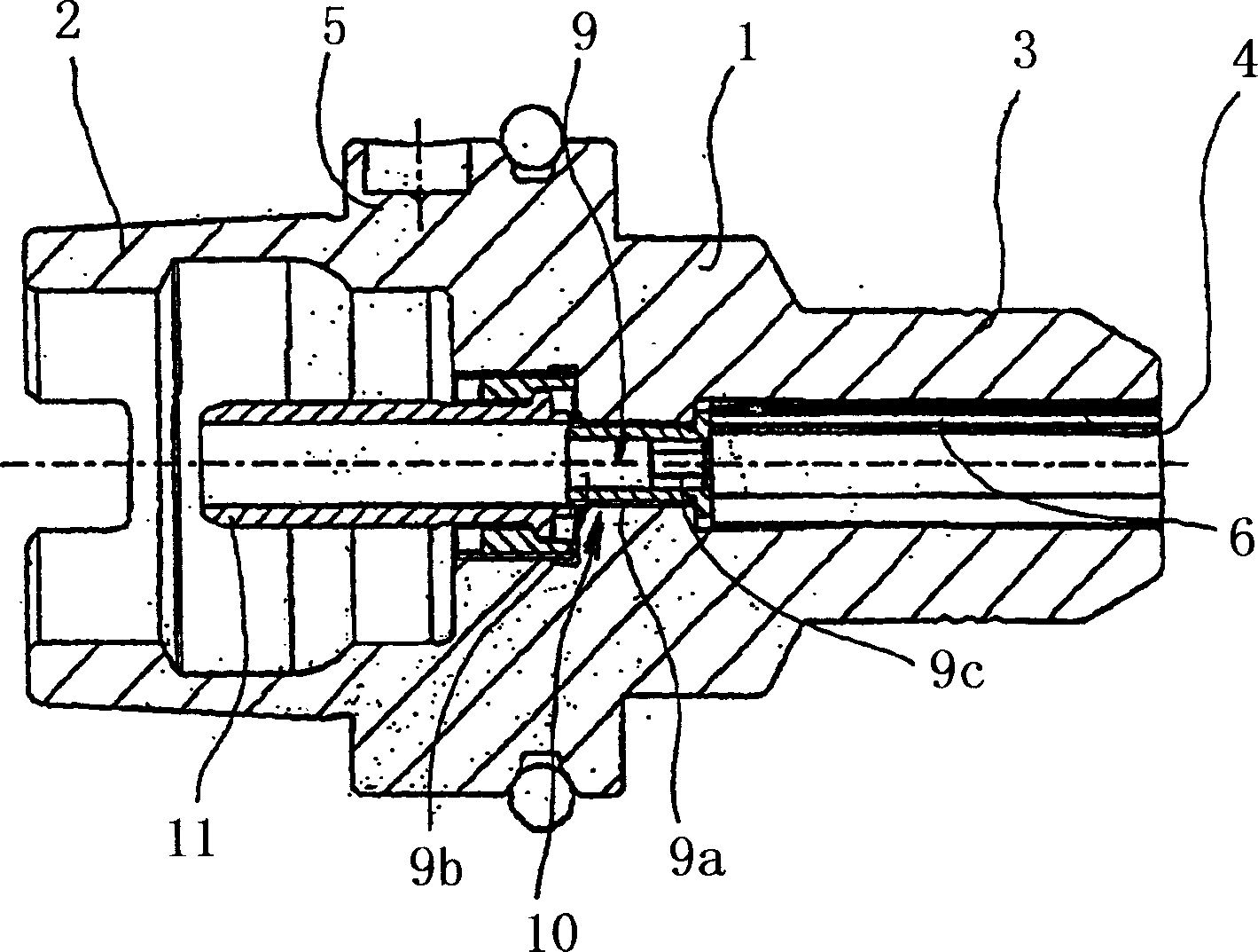
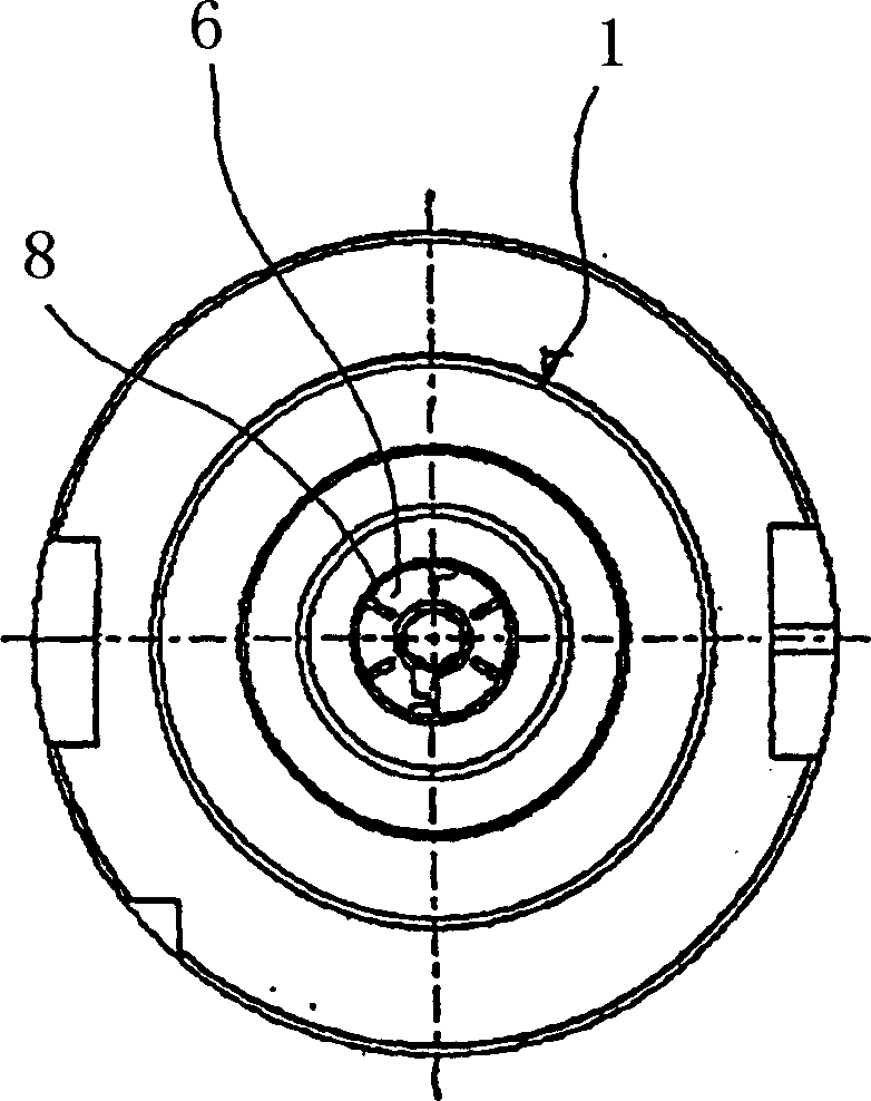
[0020] exist figure 1 and figure 2 In , an embodiment of the chuck according to the invention is shown in longitudinal section and in front view. This chuck has a chuck body 1 made of rigid material with a connection cone 2 in a known manner at one end region of the chuck body 1 for the rotary drive work of the clamping to the machine tool on the spindle. On the other end of the chuck body 1 there is provided a connecting shaft 3 with a central socket 4 into which a cylindrical shaft of a tool such as a drill or cutter can be pushed, and in the connecting cone Between 2 and the connecting shaft 4 there is a central portion 5 of increased diameter.

[0021] The chuck shown is in the form of a heat shrink chuck. Alternatively, however, an embodiment in the form of an expansion chuck is also possible, which then has an expansion clamping mechanism in a known manner in the region of the connecting shaft 3 .

[0022] Also in order to be able to use the chuck 1 to clamp the sh...


PUM

PropertyMeasurementUnit
Widthaaaaaaaaaa
Maximum widthaaaaaaaaaa

Abstract

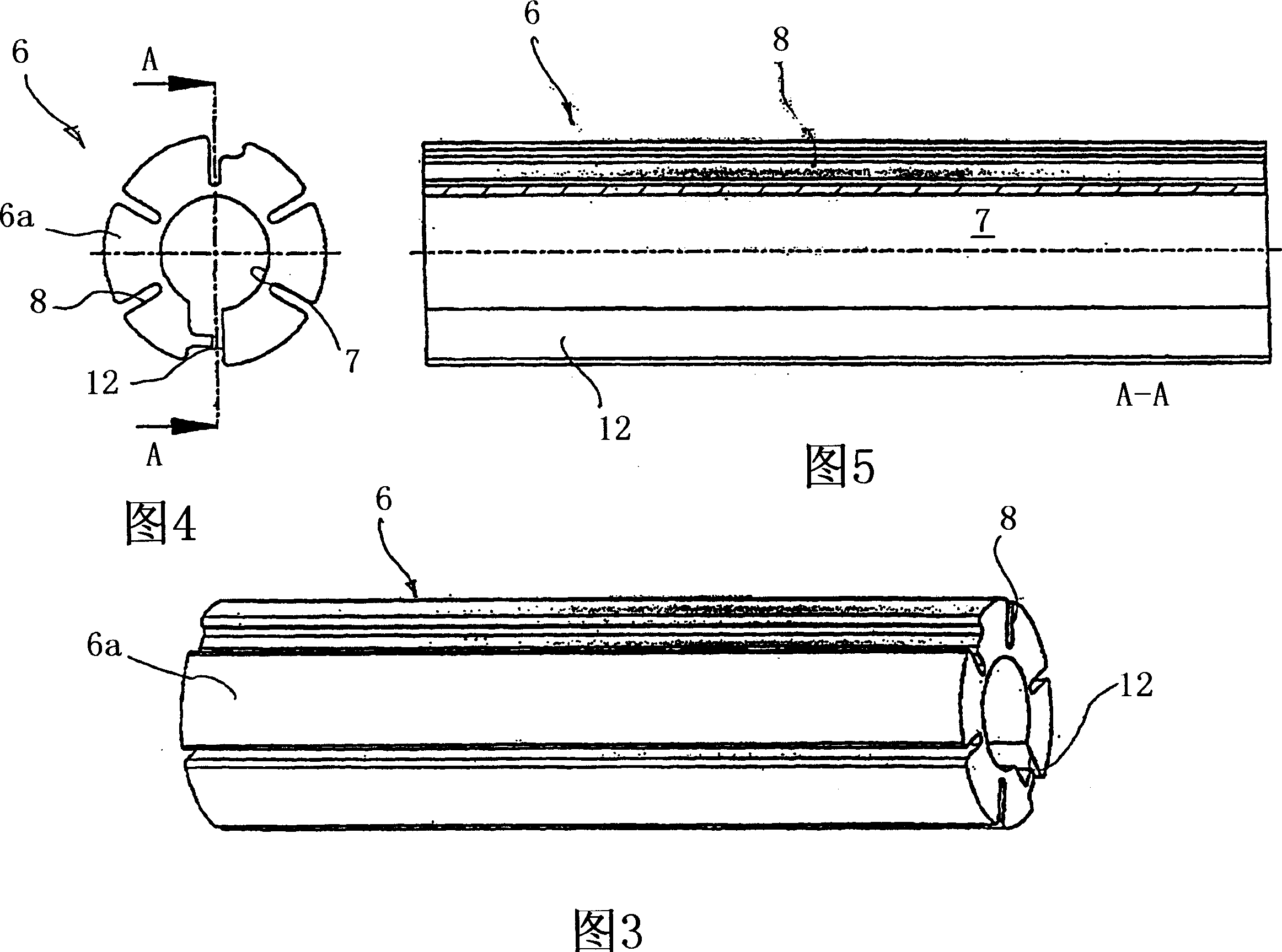
The invention relates to an intermediate bush for placing in the central location of a collet chuck having a cylindrical body, which has a central chucking bore provided in the form of a through bore, whereby the body has a number of radial slots, which are distributed along the body's outer periphery and which extend over the entire length of the intermediate bush. The invention is characterized in that the slots have a maximum width of 0.6 mm, and the outer contour, the slots and the chucking bore of the intermediate bush are eroded, and in that the body has, over its entire length, a through slot, which extends from the body's outer periphery to the inner periphery and which has a maximum width of 0.6 mm. The invention also relates to a method for producing an intermediate bush of this type.

Description

technical field [0001] The invention relates to an intermediate bushing according to the preamble of claim 1 to be inserted into the central socket of a chuck. Furthermore, the invention relates to a chuck having: a chuck body in which a central socket for the shaft of a tool to be clamped is formed; Between the end of the chuck body and the socket into which the intermediate bushing is inserted, for supplying coolant to the machine-side end of the tool which is pushed into the socket. Finally, the invention relates to a method of manufacturing an intermediate bushing. Background technique [0002] Chucks of the above-mentioned type are known in various embodiments and are used in practice to fix the shaft of a tool, for example the shaft of a drill or a tool, in place in a working spindle of a corresponding machine tool. With known chucks, which are designed, for example, as expansion chucks or heat shrink chucks, the clamping span is so limited that on the one hand the d...

Claims


Application Information

Patent Timeline
IPC IPC(8): B23B31/02B23B31/30B23B31/117B23Q11/10B23H9/00B23Q1/00F16D1/06F16D1/08
CPCF16D2001/062B23H9/00B23B31/305B23Q11/1023F16D1/06B23B2250/12B23B31/1179B23B31/028B23B2260/026F16D1/0829B23H9/005Y10T279/17564
Inventor 托马斯·雷茨巴赫
Owner SCHUNK GMBH & CO KG SPANN UND GREIFTECHN
Learn More