Method of charging low temperature liquified gas

A low-temperature liquefied gas and liquid technology, applied in container filling methods, liquid variable capacity machinery, gas/liquid distribution and storage, etc., can solve the problems of high energy, gas deterioration, etc., achieve less heat generation, shorten filling time, The effect of minimizing power costs or operating and maintenance costs

Inactive Publication Date: 2006-12-20
ULSAN CHEM
View PDF0 Cites 5 Cited by
  • Summary
  • Abstract
  • Description
  • Claims
  • Application Information

AI Technical Summary

Problems solved by technology

[0007] The conventional method of vaporizing the liquefied gas and then using a compressor to pressurize the vaporized gas and filling it into a container not only requires a lot of energy for the gasification and pressurization process, but also is used for etching in the semiconductor manufacturing process. Gas nitrogen trifluoride (NF 3 ) gas that requires high-purity gas, the possibility of gas deterioration increases

Method used


Image

  • Method of charging low temperature liquified gas

Examples


Embodiment

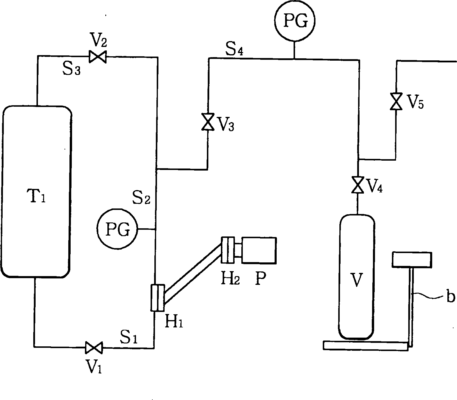
[0034] according to figure 1 The filling method of the present invention will be specifically described. The liquefied gas used in the filling test is a liquid high-purity NF condensed at low temperature 3 gas. Tank T 1 Using piping and NF 3 Manufacturing process connection, for thermal insulation, storage tank T 1 The exterior is made of a double vacuum jacket. NF stored in tanks 3 Gas, through suction piping S 1 Delivery to diaphragm pump suction port, suction piping S 1 It is also made into double-layer tubular vacuum insulated piping, and the pressure head H at the remote end of the pump is 2 A coil was installed to maintain the temperature of the remote head at -90°C by passage of a cryogenic fluid (liquid nitrogen, liquid air, etc.). The pump pressure head and the oil storage tank are filled with oil by a diaphragm pump, and the pump pressure head H 1 with remote indenter H2 Fill with dehydrated and degassed ethanol in between. Install a pressure gauge on the ...


PUM


Abstract

Disclosed is a method of charging a low temperature liquefied gas in a high pressure charging cylinder using a diaphragm pump. The method is advantageous in that it is possible to charge a low temperature liquefied gas which is to be made highly pure in a high pressure gas cylinder using a simple process in which the liquefied gas does not deteriorate and small energy is consumed.

Description

technical field [0001] The present invention relates to a filling method of a low-temperature liquefied gas which is in a gas state at normal temperature and is used for filling a high-pressure gas container under high pressure. Specifically, the present invention relates to a method for filling a high-pressure gas container with cryogenic liquefied gas using a diaphragm pump. Background technique [0002] Generally, a liquefied gas with a low boiling point is in a liquid state at a low temperature below the critical temperature. On the other hand, when it becomes above the critical temperature change, it becomes a gas state. This gas is referred to as cryogenic liquefied gas in the present invention. These liquefied gases take advantage of such characteristics, in tens to 200kg / cm 2 It is used in a gaseous state under the pressure of G and filled into a container made for high pressure. Such liquefied gases include nitrogen, oxygen, and argon that are commonly used, and...

Claims


Application Information

Patent Timeline
Patent Type & Authority Applications(China)
IPC IPC(8): F17C5/04
CPCF04B43/067Y02E60/321F17C2227/0142F04B15/08F04B43/06F17C2205/0355Y02E60/32F17C5/02
Inventor 张香子饭久保祐一金大铉金哲虎
Owner ULSAN CHEM
Why Eureka
Try Eureka