[0015] Example
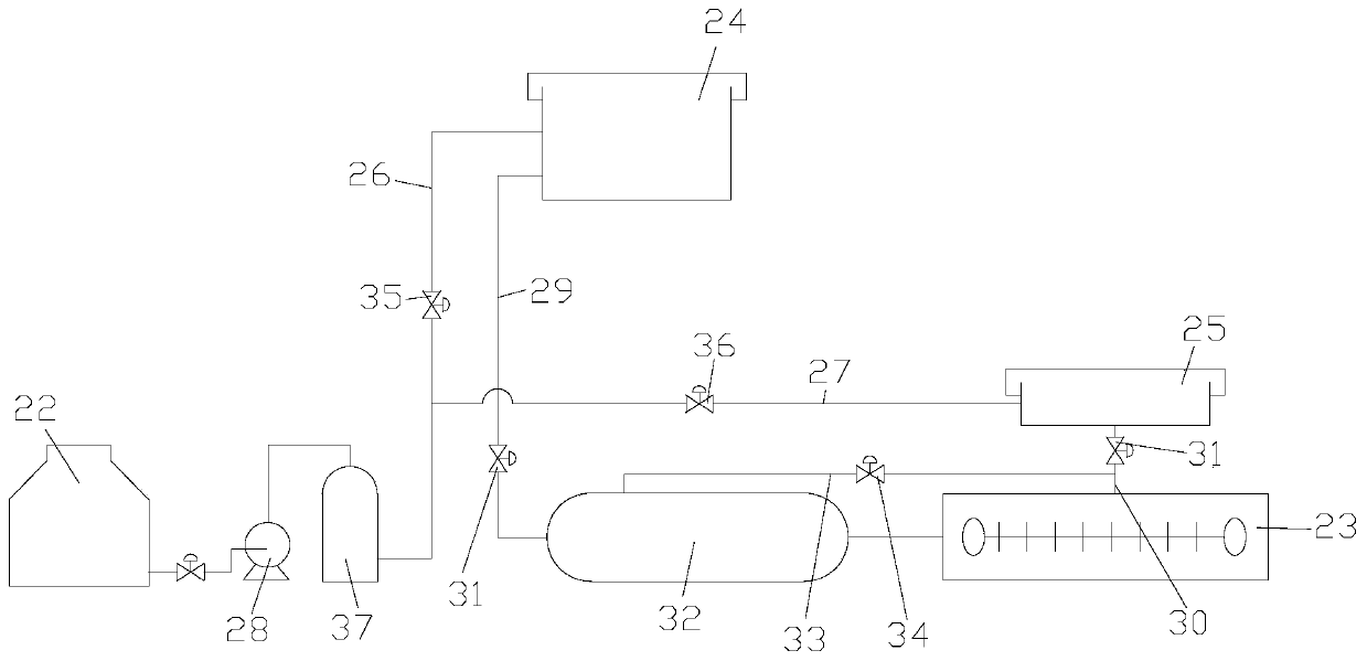
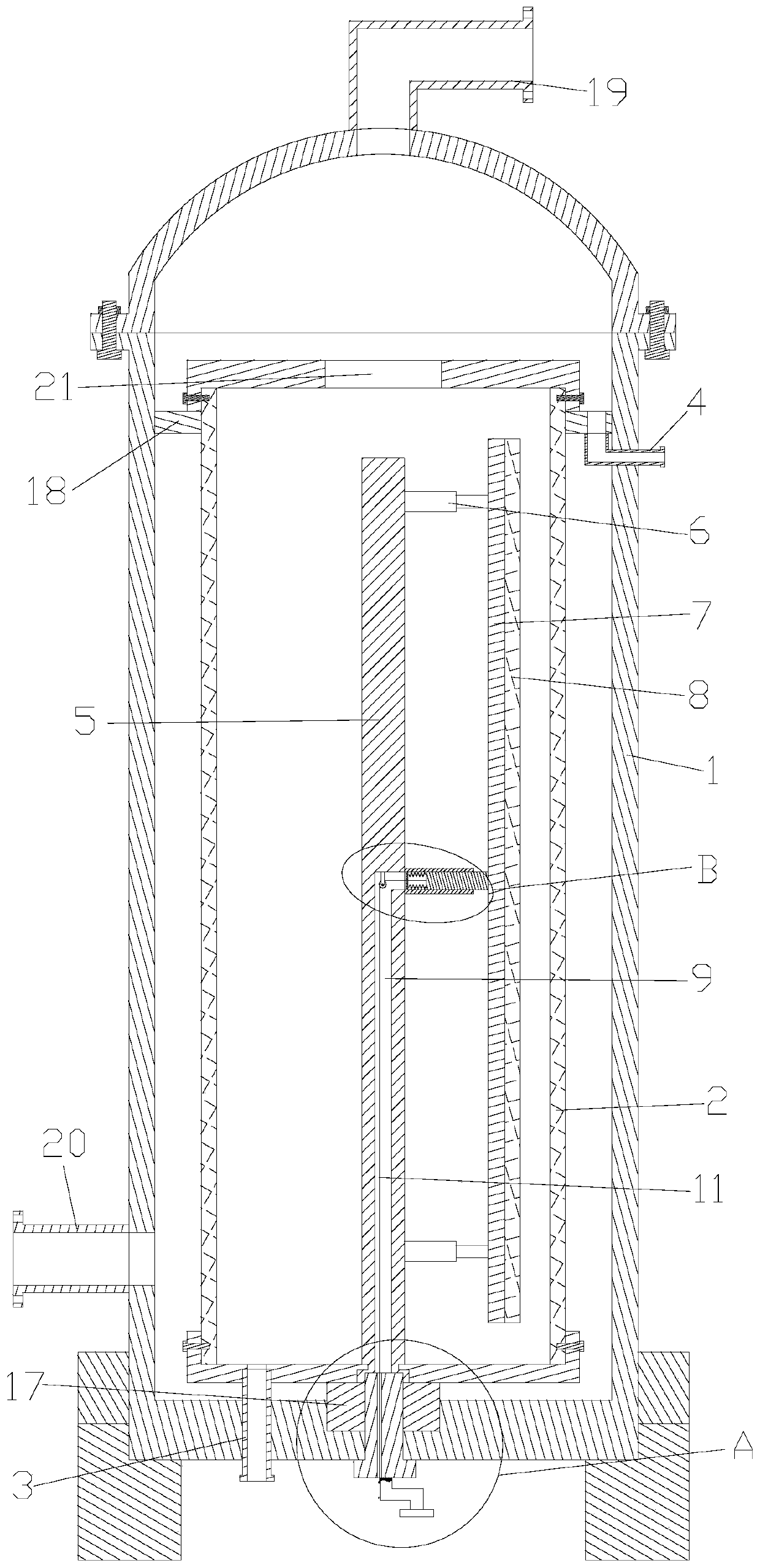
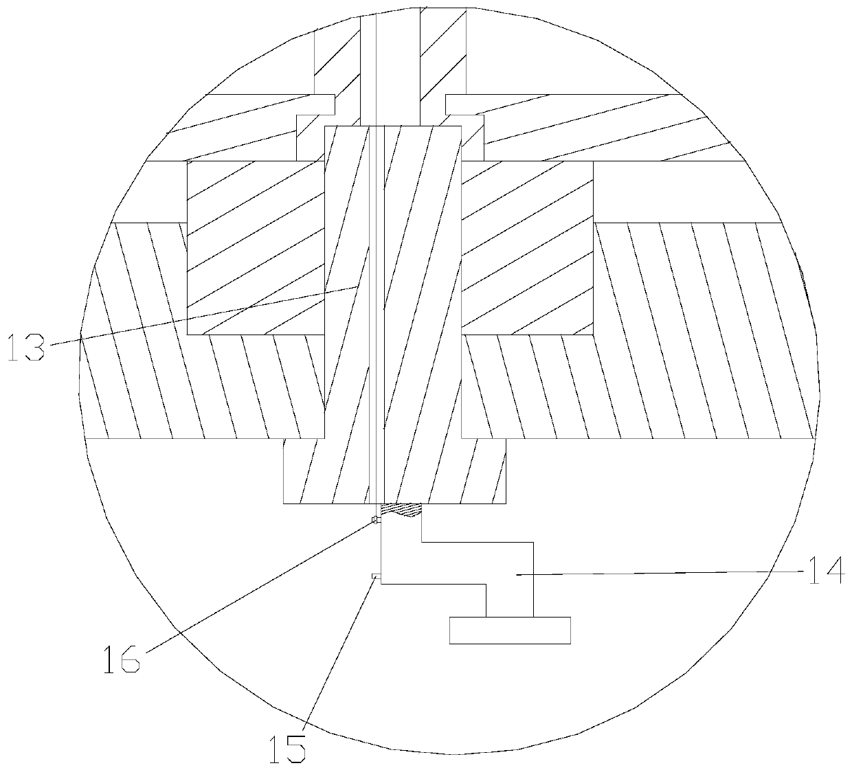
[0016] refer to Figure 1 ~ Figure 4 Shown: a kind of urea filling system for vehicles, raw material storage tank 22 and multi-head filling machine 23, high-position tank 24 and low-position tank 25 arranged from top to bottom, multi-head filling machine 23 can be 8-16 in the present embodiment Head filling machine, generally adopts 12 filling machines, the low slot 25 is positioned at about one meter above the multi-head filling machine 23, and the high slot 24 is positioned at about five meters above the multi-head filling machine 23; the raw material storage tank 22 and the high slot 24 is provided with the communication through the first pipeline 26, and the middle part of the first pipeline 26 communicates with the lower tank 25 through the second pipeline 27. The pump 28, the upper tank 24 communicate with the liquid inlet of the multi-head filling machine 23 through the third pipeline 29, the lower tank 25 communicates with the liquid inlet of the multi-head filling machine 23 through the fourth pipeline 30, and the third pipeline 29 and the first Each of the four pipelines 30 is provided with a first regulating valve 31 .
[0017] In order to distribute the vehicle urea in the upper tank 24 and the lower tank 25 evenly into the multi-head filling machine 23, the system also includes a liquid distributor 32, which is arranged on the third pipeline 29 and is located at the first The rear end of the liquid outlet of the first regulating valve 31 on the three pipes 29 and the bottom of the liquid distributor 32 communicate with the multiple liquid inlets of the multi-head filling machine 23 through a plurality of communication pipes arranged in parallel. The liquid outlet of the distributor 32 communicates with the middle part of the fourth pipe 30 with a fifth pipe 33, and the connection point between the fifth pipe 33 and the fourth pipe 30 is located behind the liquid outlet of the first regulating valve 31 on the fourth pipe 30. end, the fifth pipe 33 is provided with a second regulating valve 34 . When the high-level tank 24 or the low-level tank 25 is feeding liquid into the multi-head filling machine 23, the liquid is distributed uniformly through the liquid distributor 32, and the vehicle urea is evenly distributed through the connection mode of the liquid distributor 32 and the multi-head filling machine 23. are distributed to each independent warehouse in the multi-head filling machine 23 for filling work. A third control valve 35 located between the second pipeline 27 and the head tank 24 is provided on the first pipeline 26 , and a fourth control valve 36 is provided on the second pipeline 27 .
[0018] In order to filter the impurities in the urea for vehicles extracted in the raw material storage tank 22, a filter 37 positioned at the front end of the second pipeline 27 liquid inlets is arranged on a pipeline, and the impurities in the urea for vehicles are filtered by the filter 37. Impurities are filtered; and the system also includes a PLC controller, the PLC controller is an existing central controller, and the PLC controller is connected with the first control valve 31, the second control valve 34, the third control valve 35 and the fourth control valve 36 are connected by communication, and the communication status of the first control valve 31, the second control valve 34, the third control valve 35 and the fourth control valve 36 is controlled by the PLC controller, and then the liquid inlet of the upper tank 24 or the lower tank 25 is automatically controlled. The situation and the liquid discharge situation, and the accuracy of the filling volume has been improved, so that the filling accuracy has reached within three thousandths.
[0019] The filter in this system includes a casing 1 and a filter cartridge 2 arranged in the casing 1. The lower side of the filter cartridge 2 is connected with a backflushing liquid pipe 3 passing through the casing 1. On the filter cartridge 2 The side is connected with a backflushing liquid pipe 4 passing through the housing 1, and a rotating shaft 5 is installed in the filter cartridge 2, and the rotating shaft 5 is connected with a support block 7 parallel to the rotating shaft 5 through a plurality of telescopic rods 6, and the support block 7 A cleaning brush 8 is connected to a side close to the inner wall of the filter cartridge 2; the rotating shaft 5 is equipped with an adjusting mechanism, and the adjusting mechanism includes a handle assembly that drives the rotating shaft 5 to rotate and an adjusting assembly that adjusts a plurality of telescopic rods 6 for synchronous telescopic movement. The assembly penetrates from the bottom of the housing 1 to the bottom of the filter cartridge 2 and is splined to the filter cartridge 2; the lower end of the rotating shaft 5 is rotationally connected with the bottom of the filter cartridge 2, and the lower end of the rotating shaft 5 has a mounting groove arranged in the axial direction thereof 9. The bottom of the installation groove 9 has a through hole passing through the side wall of the rotating shaft 5. The adjustment assembly includes an elastic telescopic sleeve 10 connected between the rotating shaft 5 and the support block 7. The elastic telescopic sleeve 10 is connected with an adjustment The retractable traction rope 11, the installation groove 9 is provided with a guide wheel 12 for guiding the traction rope 11, and the free end of the traction rope 11 passes through the through hole and the installation groove 9 and freely passes through the housing 1 from the handle assembly. Bottom The bottom controls the locking state of the traction rope 11 through the fixing piece on the handle assembly.
[0020] Wherein, the handle assembly used includes a transmission shaft 13 splined with the filter cartridge 2, the lower end of the transmission shaft 13 passes through the bottom of the housing 1 and the transmission shaft 13 is connected to the housing 1 in rotation, and the lower end of the transmission shaft 13 is connected with The drive handle 14, the fixing member includes a plurality of locking rods 15 arranged at intervals along the vertical direction on the driving handle 14 and a locking ring 16 connected to the free end of the traction line; the locking ring 16 is sleeved on the locking rod 15 comes up and locks and fixes the traction rope 11; in the present embodiment, there are two locking levers 15, and when the locking ring 16 is hung on the locking lever 15 positioned on the upper side, the elastic telescopic sleeve 10 is elongated, cleaning The brush 8 is in contact with the inner wall of the filter cartridge 2, so that the cleaning brush 8 can clean up the impurities adhered to the inner wall of the filter cartridge 2; When the tube 10 shrinks, the cleaning brush 8 is out of contact with the inner wall of the filter cartridge 2, and the filter can perform the filtering work.
[0021] At the same time, the bottom of the housing 1 in this embodiment has a positioning groove, the bottom of the filter cartridge 2 is connected with a positioning column 17 embedded in the positioning groove, the transmission shaft 13 passes through the positioning column 17 to rotate freely, and the upper side of the inner wall of the housing 1 An annular support seal ring 18 is arranged along its circumference, and the filter cartridge 2 passes through the annular support seal ring 18 and resists the annular support seal ring 18 through the seal cover on the top of the filter cartridge 2; the matching design of the positioning groove and the positioning column 17 is convenient for alignment The filter cartridge 2 is installed and positioned, and the annular support seal ring 18 further positions, supports and seals the filter cartridge 2, so that an independent sealed cavity is formed above the filter cartridge 2 in the housing 1; The liquid pipe 19 is connected with the drain pipe 20 on the lower side wall of the housing 1, the sealing cover on the top of the filter cartridge 2 has a liquid guide hole 21, and the annular support seal ring 18 has a guide hole to discharge the recoil liquid. The liquid inlet of the pipe 4 is connected with the diversion hole; when the filter is filtering, the backflushing liquid inlet pipe 3 and the backflushing liquid pipe 4 are all in a sealed state, and the vehicle urea solution introduced in the liquid inlet pipe 19 enters The independent sealed cavity can be filtered through the filter cartridge 2 after entering through the liquid guide hole 21; when the filter is cleaned, the liquid inlet pipe 19 and the liquid discharge pipe 20 are in a sealed state, and the flushing pipe 3 introduced The liquid enters the filter cartridge 2, overflows from the liquid guide hole 21 into the independent sealed cavity, and is introduced into the backflush liquid pipe 4 from the guide hole to be discharged.
[0022] The elastic telescopic sleeve 10 in this embodiment includes an outer cylinder 101 connected to the rotating shaft 5 and communicated with the through hole, and an inner rod 102 slidably arranged in the outer cylinder 101 and connected to the support block 7, and a connecting block 103 is arranged in the inner cylinder , between the connection block 103 and the inner rod 102, a plurality of support springs 104 in an annular distribution are connected, and the connection block 103 is provided with a through hole for the traction rope 11 to freely pass through; 101 to adjust the length of the elastic telescopic sleeve 10, thereby adjusting the contact state between the cleaning brush 8 and the inner wall of the filter cartridge 2, and the supporting spring 104 provides reset supporting force for the inner rod 102.
[0023]When the filter is performing filtering work, the recoil inlet pipe 3 and the recoil outlet pipe 4 are in a sealed state, and the vehicle urea solution introduced in the liquid inlet pipe 19 enters the independent sealed cavity and then passes through the liquid guide hole 21 and then enters the filter. After filtering in the cylinder 2, it enters the housing 1, and then discharges from the drain pipe 20 to complete the filtering work; when the filter is cleaned, the locking ring 16 on the locking rod 15 on the lower side is hung to the On the locking rod 15 on the upper side, the inner rod 102 slides under the elastic support force of the supporting spring 104, so that the cleaning brush 8 contacts the inner wall of the filter cartridge 2, and the rotating shaft 5 is rotated by driving the handle 14, thereby making the cleaning brush 8 contact with the inner wall of the filter cartridge 2. 8. Peel off the impurities adhering to the inner wall of the filter cartridge 2, seal the liquid inlet pipe 19 and the liquid discharge pipe 20 at the same time, and connect the flushing liquid at the inlet and backflush liquid pipe 3.