Light-emitting device with an electrode arrangement

A light-emitting element and electrode arrangement technology, which is applied to electrical elements, electroluminescent light sources, electric light sources, etc., can solve problems such as increasing production costs, and achieve the effects of reducing manufacturing costs, simplifying electrical contacts, and increasing output

Inactive Publication Date: 2006-12-20
NOVALED GMBH
View PDF4 Cites 3 Cited by
  • Summary
  • Abstract
  • Description
  • Claims
  • Application Information

AI Technical Summary

Problems solved by technology

[0005] However, this OLED-based white light generation has the disadvantage that the use of OLED substructures results in increased production costs compared to other OLED lighting designs that do not require additional structures in generating OLED light.
For commercial applications of such light-emitting elements, it is disadvantageous

Method used


Image

  • Light-emitting device with an electrode arrangement
  • Light-emitting device with an electrode arrangement
  • Light-emitting device with an electrode arrangement

Examples


Embodiment Construction

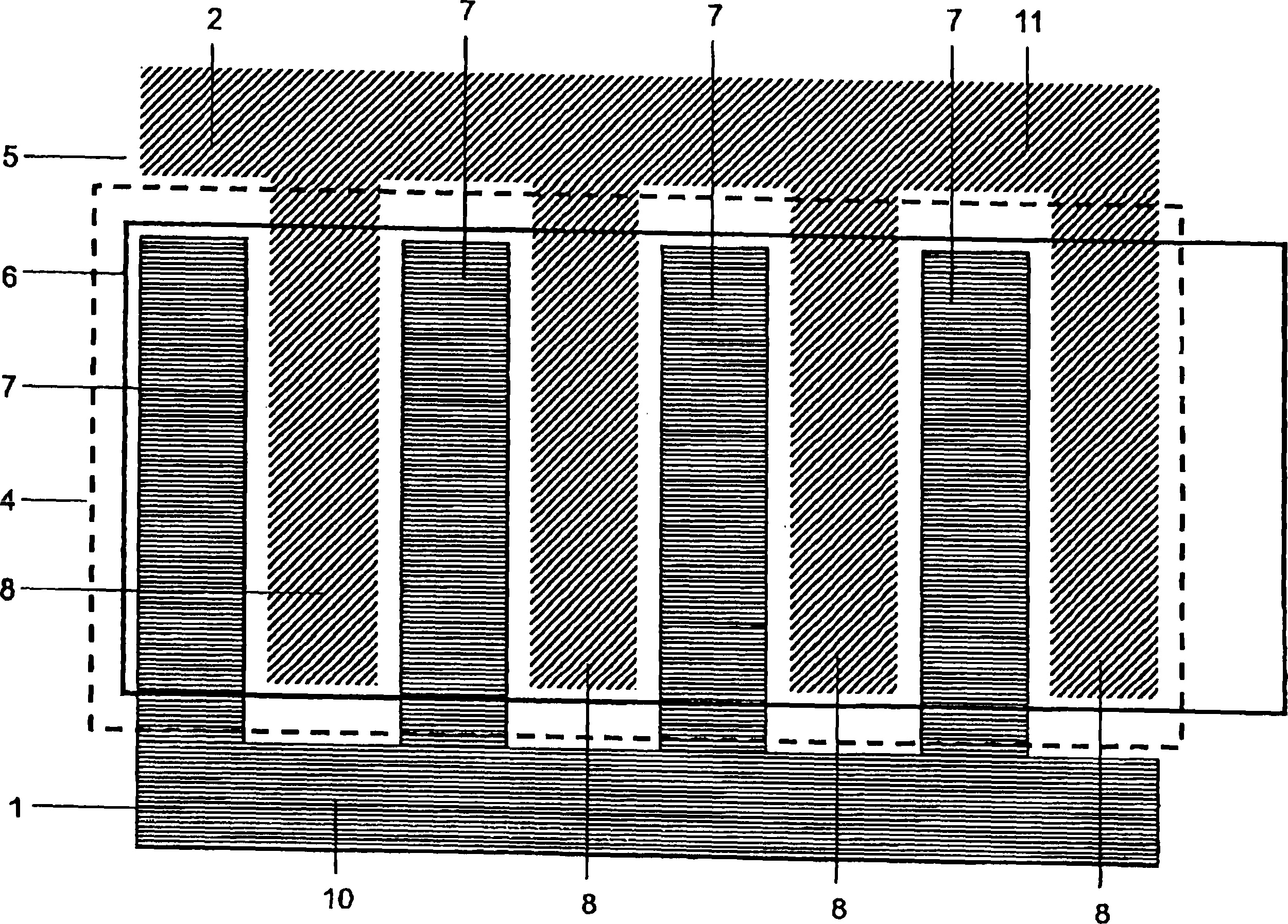
[0039] figure 1 is a schematic diagram of the electrodes of a light-emitting element through which the light-emitting organic region is excited by applying a voltage. The electrode comprises two planar partial electrodes 1 , 2 which are formed in layers adjacent to each other. Above the two partial electrodes 1 , 2 a light emitting region 4 is formed as a layer which has a plurality of organic layers which are themselves distributed across the component surface 5 and which emit light when a voltage is applied. In the illustrated embodiment, the light-emitting region 4 comprises two organic regions with different structures, each of which emits light in a specific color. A planar counter-electrode 6 is arranged above the light-emitting region 4 .

[0040] By applying a voltage to the electrodes including the partial electrodes 1, 2 and the counter electrode 6, the voltage is applied to the plurality of organic regions in the light emitting region 4, thereby emitting light. Two...


PUM


Abstract

The invention concerns a light-emitting component with an arrangement of electrodes for applying an electrical voltage to multiple organic areas, which form a light-emitting area, are distributed across a component surface and which each emit light when the electrical voltage is applied, in which the multiple organic areas are arranged between a flat-formed electrode and a flat-formed counter-electrode, where the electrode consists of a part electrode and an additional part electrode, which is electrically isolated from the part electrode and is formed so that it interlocks with it, where the electrode and the counter-electrode are formed so that they do not overlap outside the light-emitting area when looking towards the component surface.

Description

technical field [0001] The present invention relates to a light-emitting element having an electrode arrangement for applying current to a plurality of organic regions forming a light-emitting region, distributed across the surface of the element, and each region emitting light when a current is applied, wherein the plurality of organic regions The region is arranged between a flat-formed electrode and a flat-formed counter-electrode. Background technique [0002] Document DE 101 45 492 A1 describes a light-emitting element with light-emitting organic regions, which generate white light by means of an OLED (Organic Light-Emitting Diode) substructure, for example in different Produces planar spots or strips of white light at a wavelength of . The OLED substructures are contacted using separate electrodes and excited by a voltage source, whereby an optimized light mix of different colors can be obtained. [0003] The process of manufacturing such light-emitting elements nece...

Claims


Application Information

Patent Timeline
Patent Type & Authority Applications(China)
IPC IPC(8): H01L27/32
CPCH01L27/3211H01L2251/564H01L27/3204H10K59/86H10K59/35H10K71/841H05B33/26
Inventor 扬·比恩施托克斯文·穆拉诺
Owner NOVALED GMBH
Why Eureka
Try Eureka