
Method for installing an elevator

A technology for elevators and elevator shafts, applied in the field of elevators, can solve problems such as the expansion of car boxes, and achieve the effects of reducing installation time, saving installation time, and reducing installation time.

Inactive Publication Date: 2006-12-20
KONE CORP
View PDF3 Cites 3 Cited by
  • Summary
  • Abstract
  • Description
  • Claims
  • Application Information

AI Technical Summary

Problems solved by technology

As is known, increasing the size of such traction sheave elevators is practically impossible since the elevator car and counterweight already occupy the cross-sectional area of ​​the elevator shaft and the car cannot reasonably be enlarged

Method used


Image

  • Method for installing an elevator
  • Method for installing an elevator
  • Method for installing an elevator

Examples


Embodiment Construction

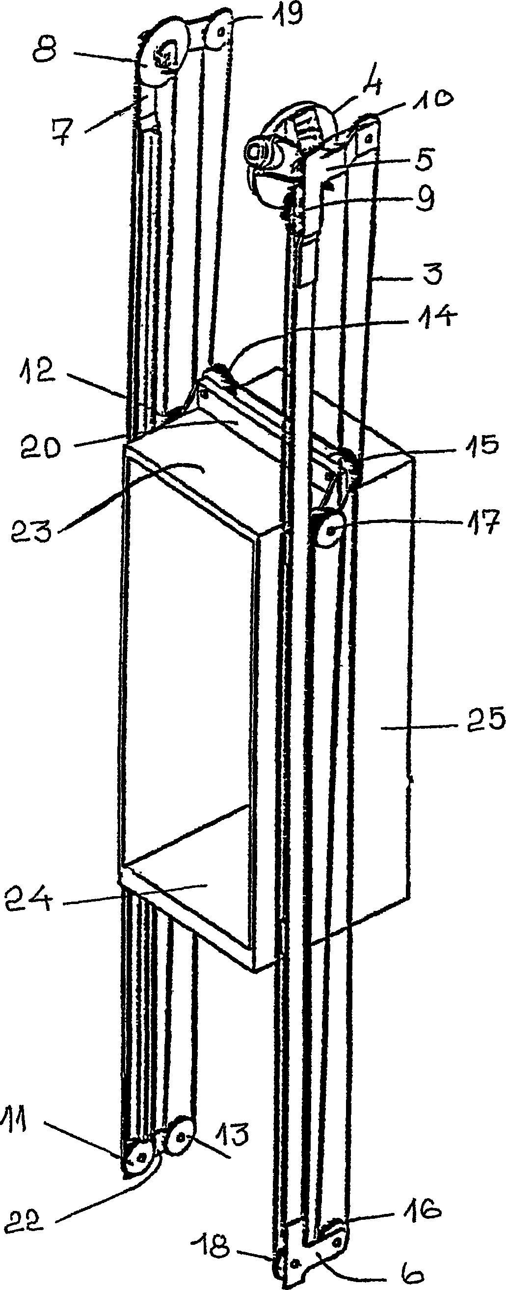
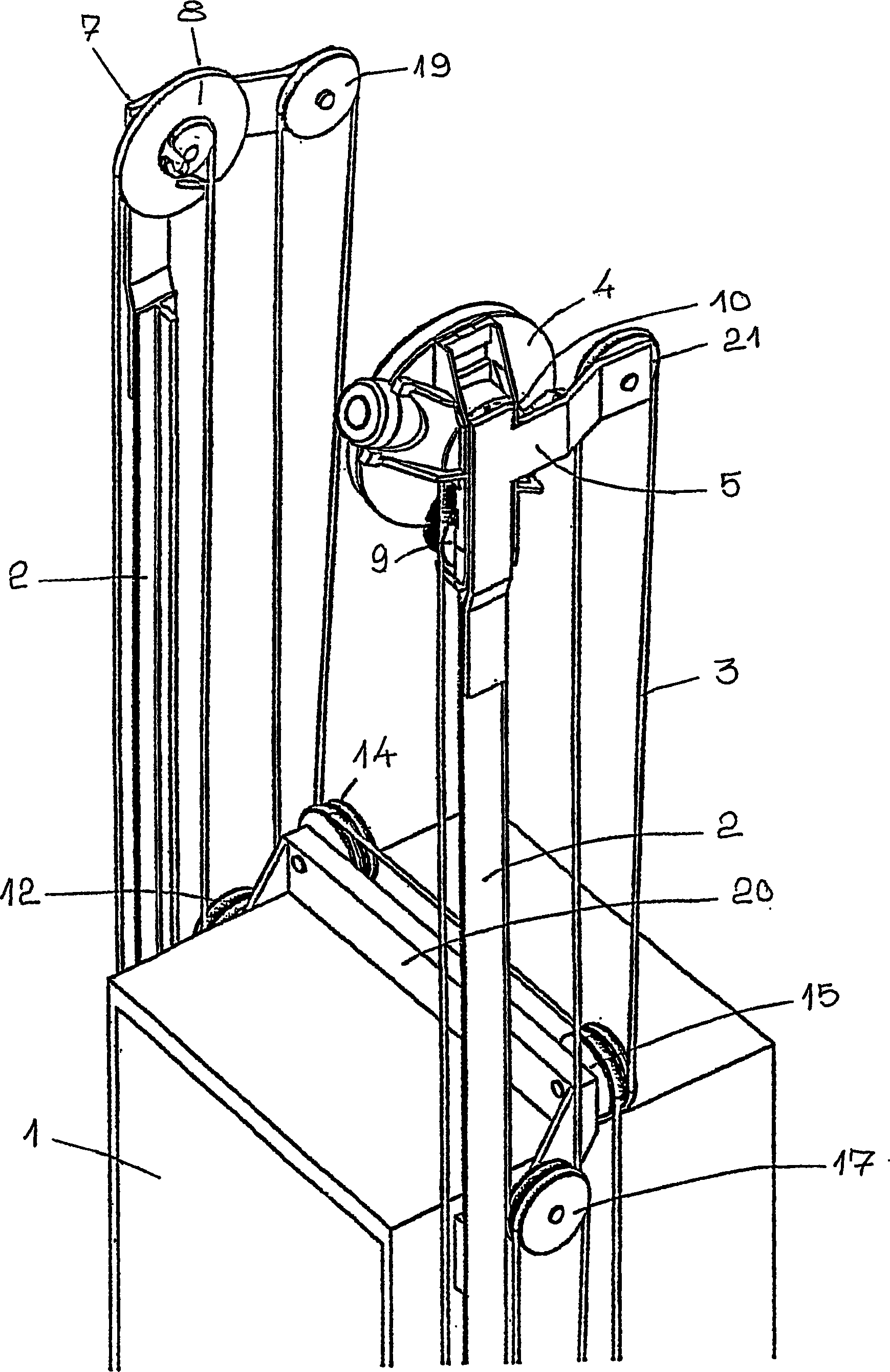
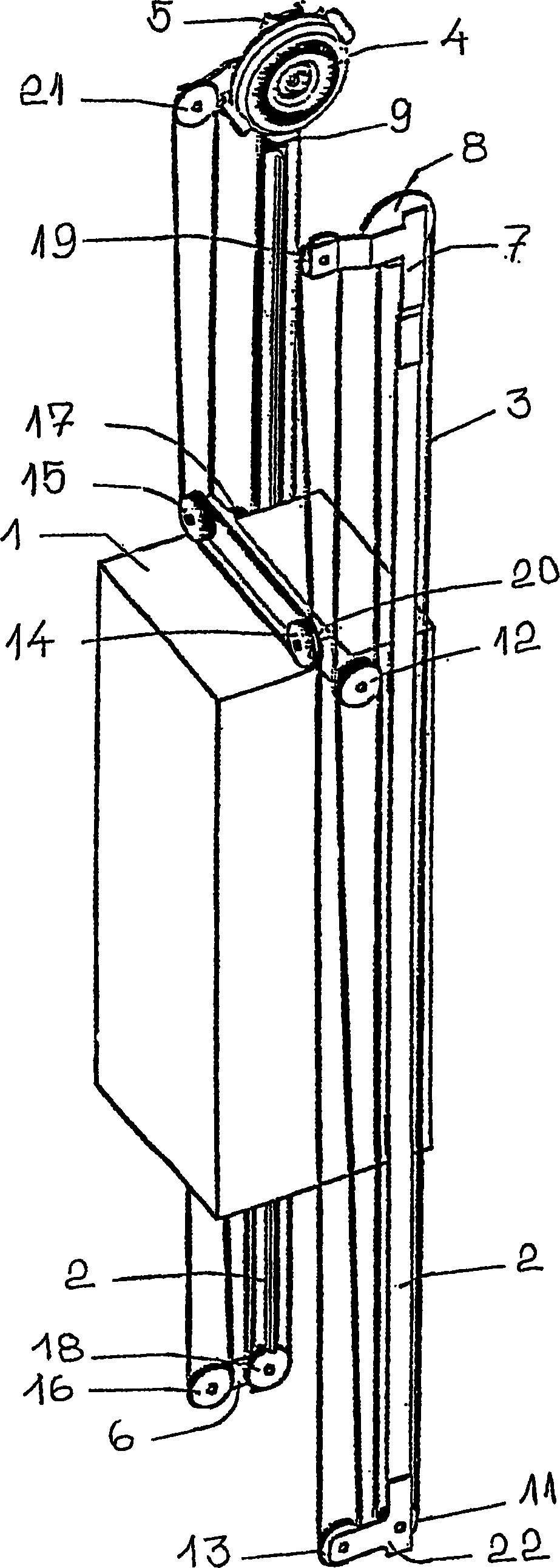
[0056] figure 1 , 2 and 3 represent the elevator structure according to the invention. The elevator is preferably an elevator without a machine room and the drive machine is arranged in the elevator shaft. The elevator shown in the figures is a traction sheave elevator without counterweight and with the machine on top, wherein the elevator car 1 moves along guide rails 2 . exist figure 1 , 2 and 3, the hoisting rope is extended in the following manner: one end of the hoisting rope is fixed on a wheel of small diameter contained in the compensating mechanism that functions as a compensating device 8, said wheel being fixedly mounted on a second large diameter wheel, the second wheel is included in the compensating mechanism 8 . Via a support element 7 fixed immovably on an elevator guide rail 2 , the compensating mechanism 8 as compensating device has been fixedly mounted on the elevator shaft. From the small diameter wheel of the compensating mechanism 8, the hoisting ro...


PUM

PropertyMeasurementUnit
strengthaaaaaaaaaa

Abstract

An elevator, preferably an elevator without counterweight, comprising a number of diverting pulleys in the upper part of an elevator shaft or equivalent, a number of diverting pulleys in the lower part of the elevator shaft and a number of diverting pulleys on an elevator car, is installed in such manner that at least some of the diverting pulleys for the upper part are rigged in the lower part of the elevator shaft and at least some of the diverting pulleys from which the passage of the ropes is directed upwards are rigged at the same time. The diverting pulleys for the upper part thus rigged are raised in the rigged state to the upper part of the elevator shaft or equivalent and mounted in place.

Description

technical field [0001] The invention relates to a method as defined in the preamble of claim 1, to an elevator resulting from the method and to an elevator as defined in the preamble of claim 10. Background technique [0002] One aim of research and development work related to elevators is the efficient and economical use of building space. In recent years, among these research and development efforts, various machine room-less elevator solutions have been proposed. Good examples of machine room-less elevators are disclosed in the specifications of EP0631967(A1) and EP0631968. Since the elevators described in these specifications do not require the enlargement of the elevator shaft, the space required in the elevator machine room in the building can be reduced, and they are quite efficient in the use of space. In the elevators disclosed in these specifications, the machine is compact at least in one direction, but in other directions it may have larger dimensions than the ...

Claims


Application Information

Patent Timeline
Patent Type & Authority Applications(China)
IPC IPC(8): B66B19/00B66B11/08
CPCY10S187/90B66B11/08B66B19/007B66B19/02Y10T29/49828B66B7/06B66B11/04
Inventor 奥斯莫·比约尼埃斯科·奥兰科托伊沃·范塔嫩乔马·穆斯塔拉蒂
Owner KONE CORP
Learn More