Automatic slurry deferrization machine

A technology of iron remover and slurry, which is applied in magnetic separation, solid separation, wet separation, etc., can solve the problems of poor iron removal effect, high power consumption, inaccurate positioning of drums, etc.

Inactive Publication Date: 2006-12-27
杭州威呢斯陶瓷有限公司
View PDF0 Cites 20 Cited by
  • Summary
  • Abstract
  • Description
  • Claims
  • Application Information

AI Technical Summary

Problems solved by technology

[0002] At present, the electromagnetic iron remover and the drum iron remover are commonly used to remove iron filings in the slurry. The disadvantages of its structure are: 1. Using electricity to form a magnetic field to absorb iron filings consumes a lot of power. The electric power of electric iron removal is 15KW. Calculated on the basis of 330 working days, 90% working efficiency, and 0.5 yuan for electricity, that is, 15*24*330*0.9*0.5=53460 yuan; 2. If the cleaning solenoid valve of the double-drum iron remover fails, the cleaning water will run completely If it goes into the slurry, or the positioning of the roller is not accurate, the effect of iron removal will not be good.

Method used


Image

  • Automatic slurry deferrization machine
  • Automatic slurry deferrization machine
  • Automatic slurry deferrization machine

Examples


Embodiment Construction

[0020] The present invention will be described in further detail below in conjunction with the accompanying drawings and embodiments.

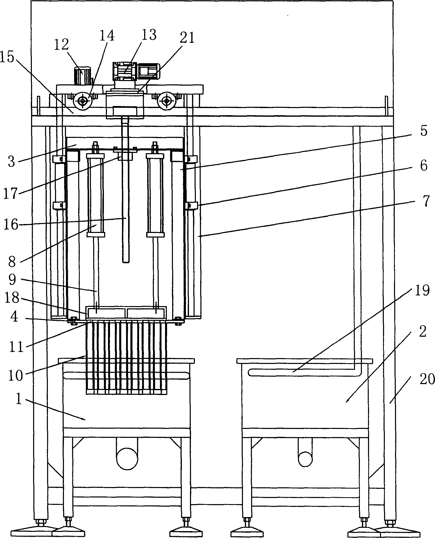
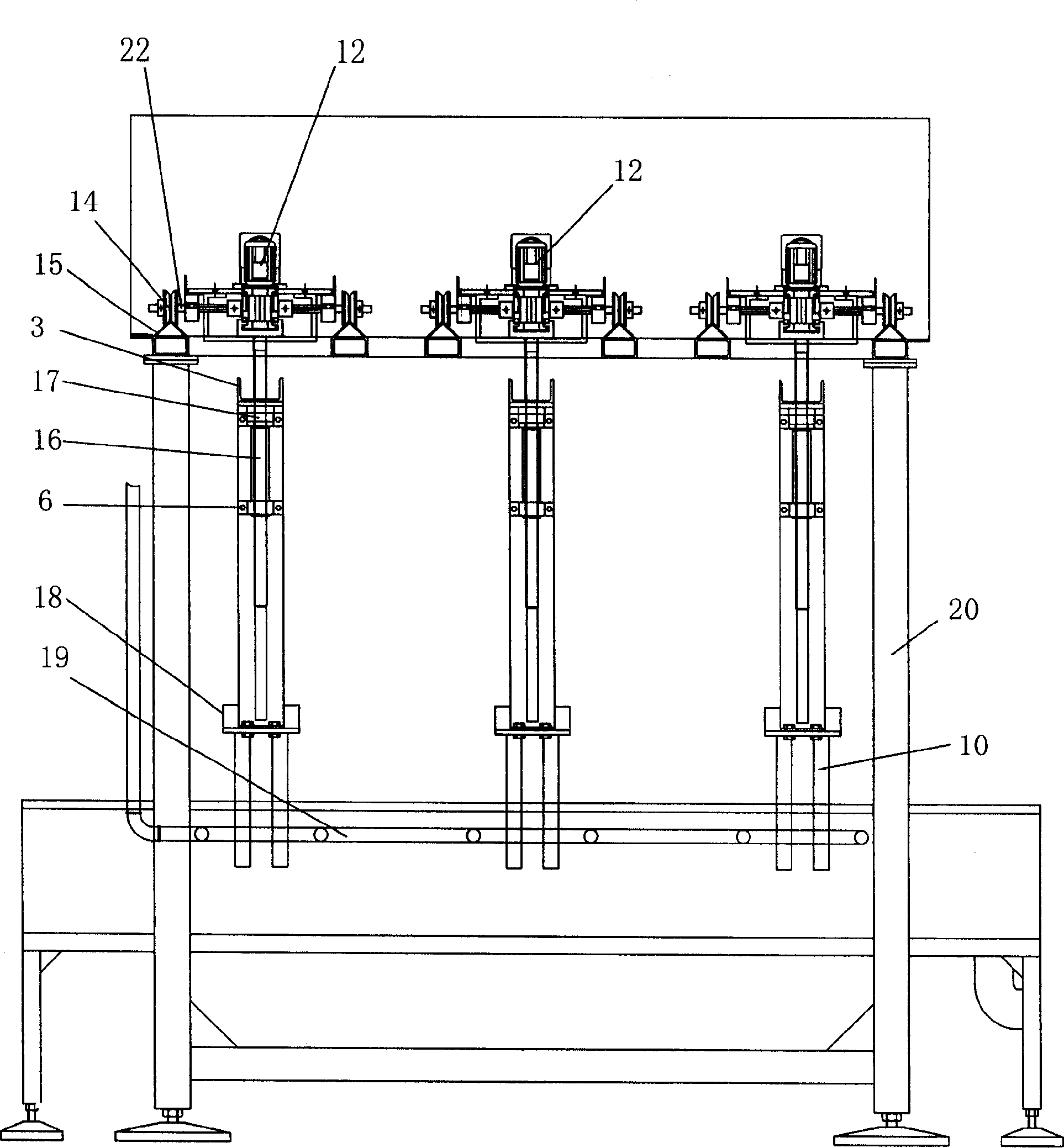
[0021] This automatic slurry iron remover mainly includes:

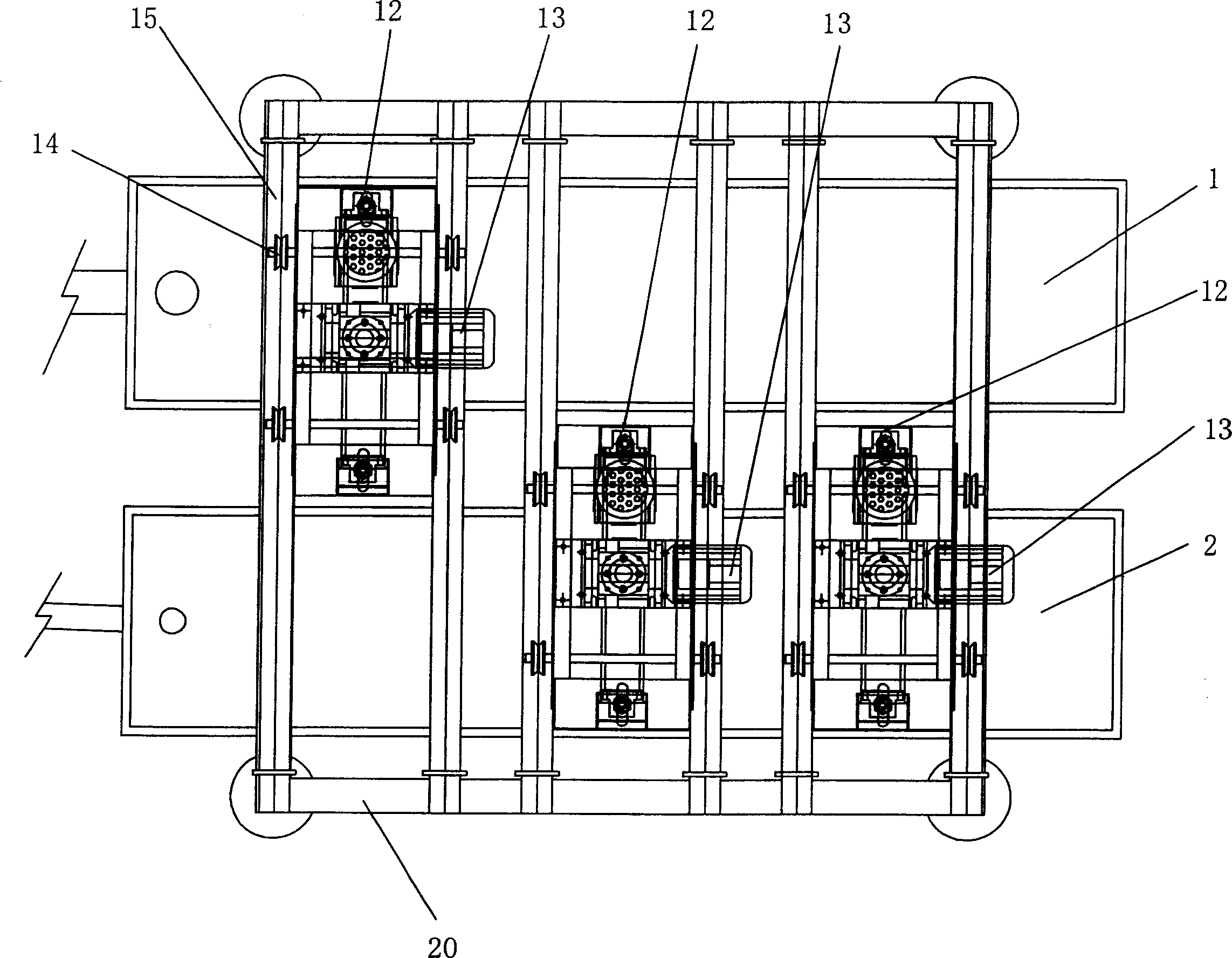
[0022] A slurry tank 1 for removing iron filings in the slurry, one end of the slurry tank 1 is provided with a slurry inlet, and the other end is provided with a slurry outlet;

[0023] A cleaning tank 2 is used to clean the iron filings adsorbed on the magnetic bar casing 10. The cleaning tank 2 is provided with a flushing water pipe 19, and the flushing water pipe 19 is connected to the water pump;

[0024] An iron frame assembly mainly includes a top plate 3, a bottom plate 4 and side plates 5 on both sides, the side plates 5 are slidingly matched with the upper and lower guide sliding rods 7 through the sliding sleeve 6;

[0025] A group of permanent magnet rods 11 are fixedly connected with the up and down lifting device;

[0026] A group of magnetic rod sleeves 10 are fixedl...


PUM


Abstract

The invention relates to an automatic slurry iron-removing machine, formed primarily from a slurry tank for removing iron dust in slurry; a cleaning tank for cleaning iron dust; an iron support assembly primarily comprising a top plate, a bottom plate, and two double-sided side plates; a group of permanent magnet iron rod fixed and connected to upper and lower lifting device; a group of magnetic rod sleeve fixed and connected to bottom plate for absorbing iron dust with permanent magnet iron rod; a sliding device for actuating the iron support assembly to slide between the slurry tank and cleaning tank; a lifting device for actuating the iron support assembly to move up and down; and a lifting device for actuating a group of permanent magnet iron rod to lift in magnetic rod sleeve. The advantage effect lies in : 1. compared to electric iron removal process, the slurry can not be polluted by cleaning water and cleaning is convenient; 2. permanent magnet iron can be replaced conveniently according to flow rate of slurry; 3. compared to conventional electric iron removal process, the cost of electricity is very low; 4. cleaned water can be reused after precipitation.

Description

technical field [0001] The invention relates to a device for removing iron filings, mainly an automatic slurry iron remover. Background technique [0002] At present, the electromagnetic iron remover and the drum iron remover are commonly used to remove iron filings in the slurry. The disadvantages of its structure are: 1. Using electricity to form a magnetic field to absorb iron filings consumes a lot of power. The electric power of electric iron removal is 15KW. Calculated on the basis of 330 working days, 90% working efficiency, and 0.5 yuan for electricity, that is, 15*24*330*0.9*0.5=53460 yuan; 2. If the cleaning solenoid valve of the double-drum iron remover fails, the cleaning water will run completely If it goes into the slurry, or the positioning of the roller is not accurate, the iron removal effect will not be good. Contents of the invention [0003] The present invention aims to solve the above-mentioned existing shortcomings, and provides an automatic slurry ...

Claims


Application Information

Patent Timeline
Patent Type & Authority Applications(China)
IPC IPC(8): B03C1/02B03B7/00
Inventor 毛国华冯俊强何永清
Owner 杭州威呢斯陶瓷有限公司
Why Eureka
Try Eureka