Evaporating and cooling system of electric vibration testing bench

A technology of evaporative cooling and electric vibration, which is applied in the cooling of instruments, measuring devices, instruments, etc., can solve the problems of waterway blockage, water leakage, short circuit and leakage, etc., and achieve energy saving, small heat exchange area and reduced leakage the effect of the possibility

Active Publication Date: 2006-12-27
SUZHOU SUSHI TESTING INSTR CO LTD
View PDF0 Cites 8 Cited by
  • Summary
  • Abstract
  • Description
  • Claims
  • Application Information

AI Technical Summary

Problems solved by technology

However, the disadvantages of this cooling method are: 1. Due to the generation of scale and the deposits such as copper oxide and cuprous oxide generated by the oxidation of the hollow wire and oxygen ions in the water, the waterway is blocked, and then the winding is locally overheated and burned.
2. The circulating water joint and each sealing point are prone to water leakage due to water pressure, resulting in the

Method used


Image

  • Evaporating and cooling system of electric vibration testing bench
  • Evaporating and cooling system of electric vibration testing bench
  • Evaporating and cooling system of electric vibration testing bench

Examples


Embodiment 1

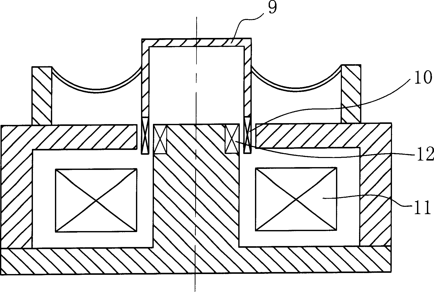
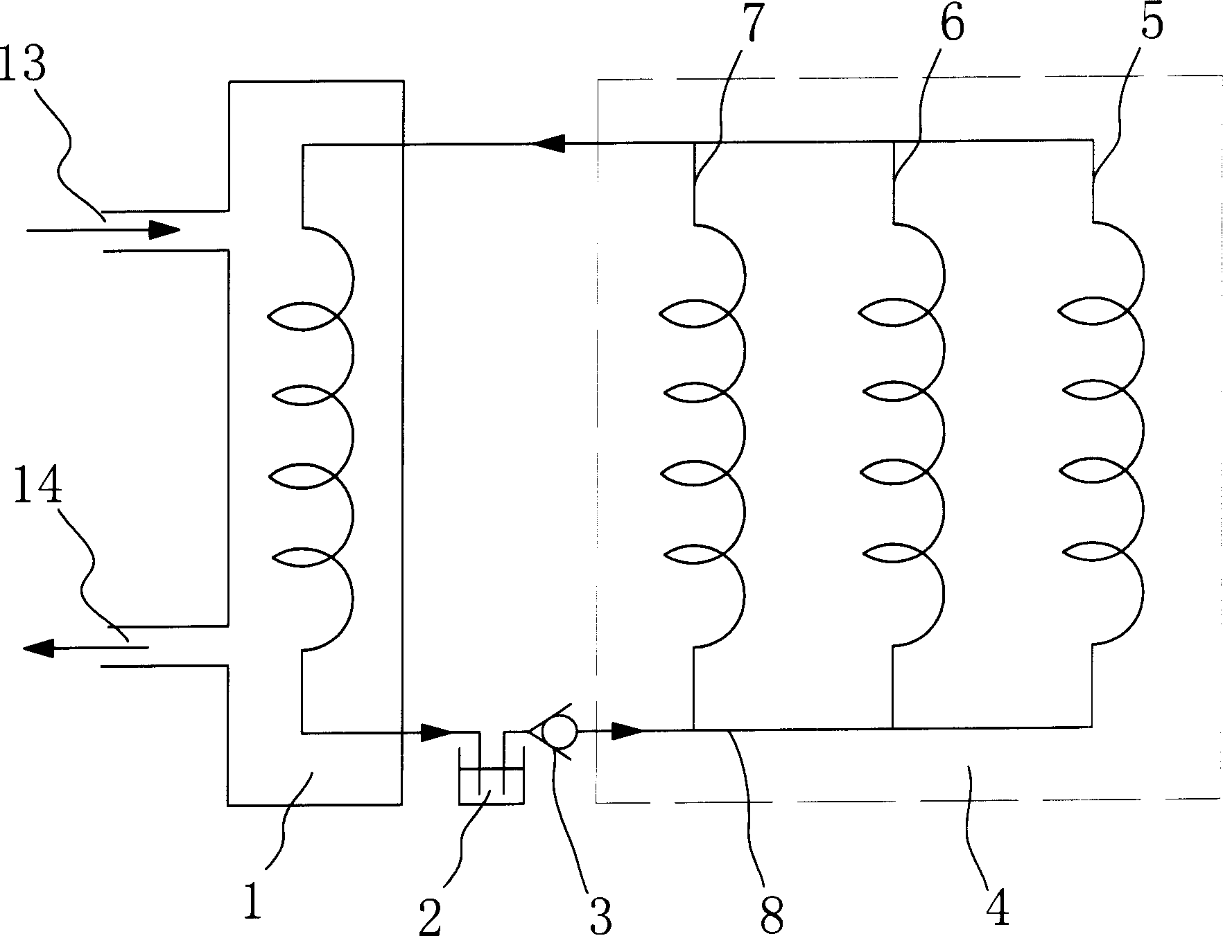
[0051] Embodiment one: see figure 2 As shown, an evaporative cooling system of a large-thrust electrodynamic vibration test bench consists of two parts: a cooling medium 8 and a circulating cooling circuit. The cooling medium is a fluorocarbon compound with a boiling point of 50-60°C, specifically one of R-113, FLA, FF31-A, and FF31L. The circulating cooling circuit is composed of a cooling channel, a heat exchanger 1, a liquid storage tank 2, and a one-way valve 3 in series through pipelines in sequence, wherein the cooling channel is connected in parallel by the excitation coil cooling channel 7, the driving coil cooling channel 6 and the short-circuit ring cooling channel 5 constitute. The drive coil cooling channel 6 is the inner tube of the hollow drive coil, which adopts a single-input and single-out design, such as Figure 4 As shown, the entire hollow drive coil body is used as the coil winding, and the inner tube is used as a cooling channel. The excitation coil c...

Embodiment 2

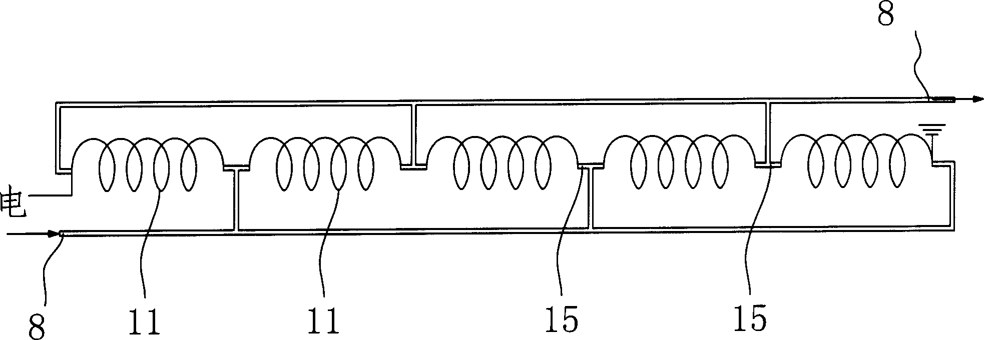
[0053] Embodiment two: see Figure 5 As shown, an evaporative cooling system of a large-thrust electrodynamic vibration test bench consists of two parts: a cooling medium 8 and a circulating cooling circuit. The difference from the first embodiment is that the cooling channel of the excitation coil adopts the immersion design (suitable for very high-power electric platforms, F>30T). The immersion design is to seal the excitation coil 11 of the electric table in a common coil form in a cavity filled with a cooling medium 8, such as Image 6 As shown, that is, the excitation coil 11 is immersed in a closed cavity 16 as a whole, and the closed cavity 16 serves as a cooling channel. In addition, an interlayer is arranged on the periphery of the airtight cavity 16, and cooling water is passed through the interlayer to improve the cooling effect. This structure can be applied to extra-large electric vibrating tables (for example, thrust F>40T), and the key is to keep the working p...


PUM

PropertyMeasurementUnit
Boiling pointaaaaaaaaaa

Abstract

The invention relates to an electric vibration test table vaporize cooling system, wherein it uses fluorocarbon whose boiling point is 50-60Deg. C as cooling medium; uses exciting coil and driving coil cooling channel to be filled into the exciting coil and driving coil of electric vibration table; via boiling medium, absorbs the hidden heat to cool the electric vibration table; the cooling medium is heated and vaporized at the exciting and driving coils to be condensed by heat exchanger (condenser) without compression; uses the secondary cooling water to emit the heat in normal temperature; the boiled medium will change density, to utilize the changes of absorbed heat and medium density to generate pressure difference, to form self-circulated power; therefore, the invention can avoid additional power, to circulate the medium in cooling system, to realize self-circulated vaporization cooling. The invention has high efficiency and high reliability.

Description

technical field [0001] The invention relates to an electrodynamic vibration test device in an environmental mechanical test, in particular to an evaporative cooling system for an excitation coil, a drive coil and a short-circuit ring in an electrodynamic vibration test bench. This cooling system is especially suitable for high-thrust electric vibration tables, providing efficient cooling. Background technique [0002] Electrodynamic vibration test bench (hereinafter referred to as electrodynamic vibration table) is a kind of equipment for vibration simulation test of products or components. It is designed using the principle of electromagnetic vibration, and its structure is mainly composed of table body, magnetic cylinder, excitation coil, moving coil, guide wheel structure and air spring. Among them, the excitation coil is fixedly installed in the table body, and a sufficiently strong constant magnetic field is generated in the working air gap after being energized, and i...

Claims


Application Information

Patent Timeline
IPC IPC(8): G01N3/317G12B15/02
Inventor 朱江峰钟琼华
Owner SUZHOU SUSHI TESTING INSTR CO LTD
Why Eureka
Try Eureka