Hydraulic empty container piling crane

A technology for stackers and containers, applied to lifting devices, etc., can solve problems such as increased operating costs, large power waste, and low work efficiency, and achieve the effects of improving operational safety and reliability, improving transmission efficiency, and reducing labor intensity

Inactive Publication Date: 2007-01-03
SANY HEAVY IND CO LTD (CN)
View PDF0 Cites 12 Cited by
  • Summary
  • Abstract
  • Description
  • Claims
  • Application Information

AI Technical Summary

Problems solved by technology

However, the disadvantage of this structure is that when the container stacker is operating, the traveling speed of the traveling device is usually in the range of 0-14Km / h, depending on the working characteristics of the hydraulic torque converter and the transmission of the hydraulic torque converter It can be seen from the characteristics that when running at low speed, this kind of hydraulic transmission generates a lot of heat, the transmission efficiency of the whole machine is low (usually between 60% and 80%), and a special radiator needs to be configured, resulting in a large waste of power
[0004] 2. The spreaders of the container lifting equipment on the container empty container stacker are directly connected with the stacker mast through the transmission chain. Through the transmission of the transmission chain, the spreader can move up and down along the vertical guide rail of the mast to complete the alignment. However, the spreaders of this structure do not have the function of rotation, so these spreaders cannot perform rotation positioning in a one-dimensional plane by themselves, and can only rely on the stacker connected to it. The adjustment is made by the driving chassis of the stacker, which drives the mast and the spreader to adjust
In this case, when using the container spreader of the stacker for container stacking, the driver will spend a long time and constantly adjust the machine position of the stacker, and during the adjustment process, the stacker must turn the wheels repeatedly to realize the container spreader. Accurate box alignment and stacking, so the driver's labor intensity is high, work efficiency is low, tire wear is serious, and operating costs are increased
[0005] 3. The height of the cab of the existing empty container stacker is fixed and cannot be adjusted
[0007] 5. During the stacking process of the empty container stacker, the stacker may work in an overweight state due to human error in detection or the material in the box is not emptied, which will cause equipment damage and even cause security incident
However, in the existing stacker products, there are basically no corresponding safety protection measures

Method used


Image

  • Hydraulic empty container piling crane
  • Hydraulic empty container piling crane
  • Hydraulic empty container piling crane

Examples


Embodiment Construction

[0044] The present invention will be described in further detail below in conjunction with the accompanying drawings and specific embodiments.

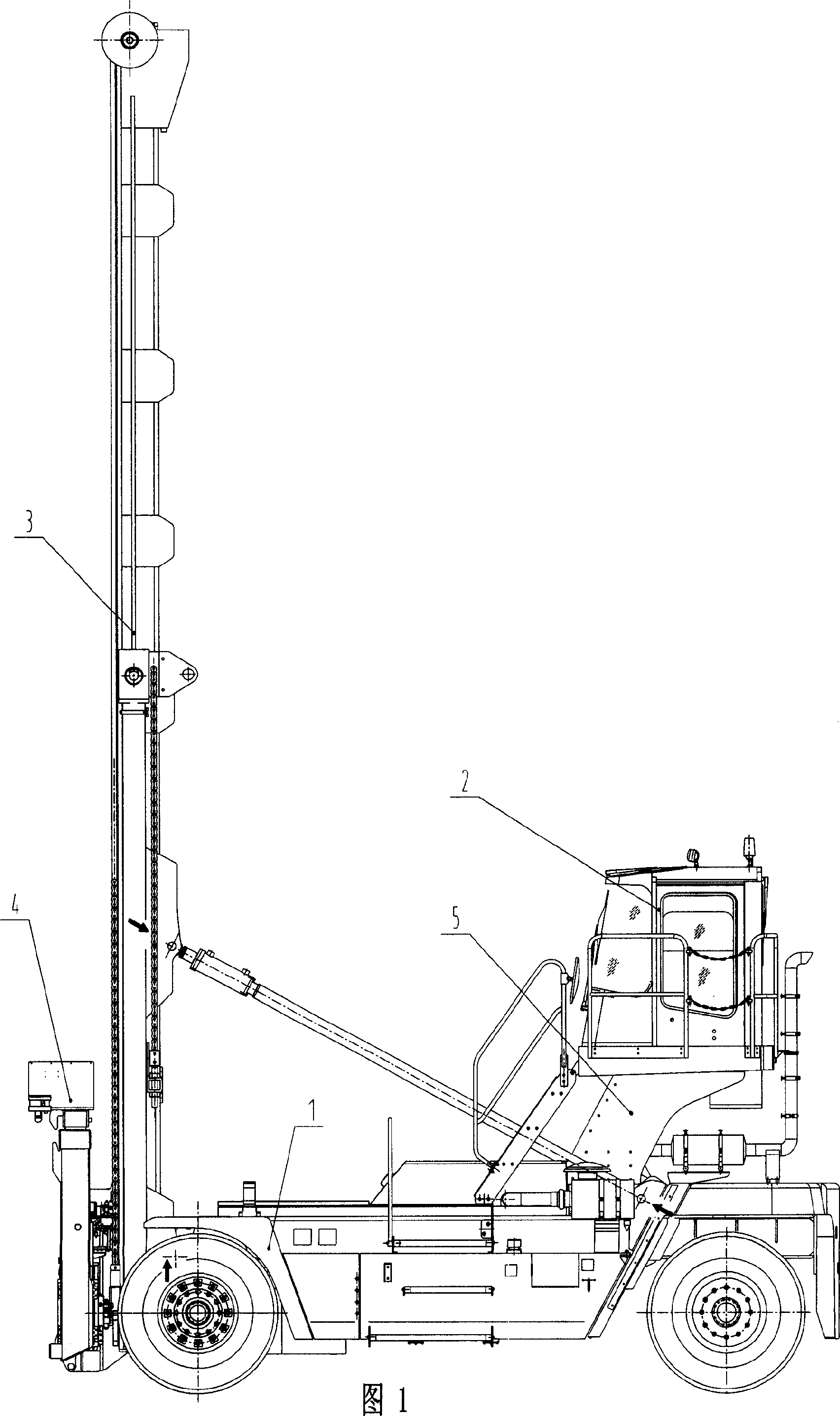
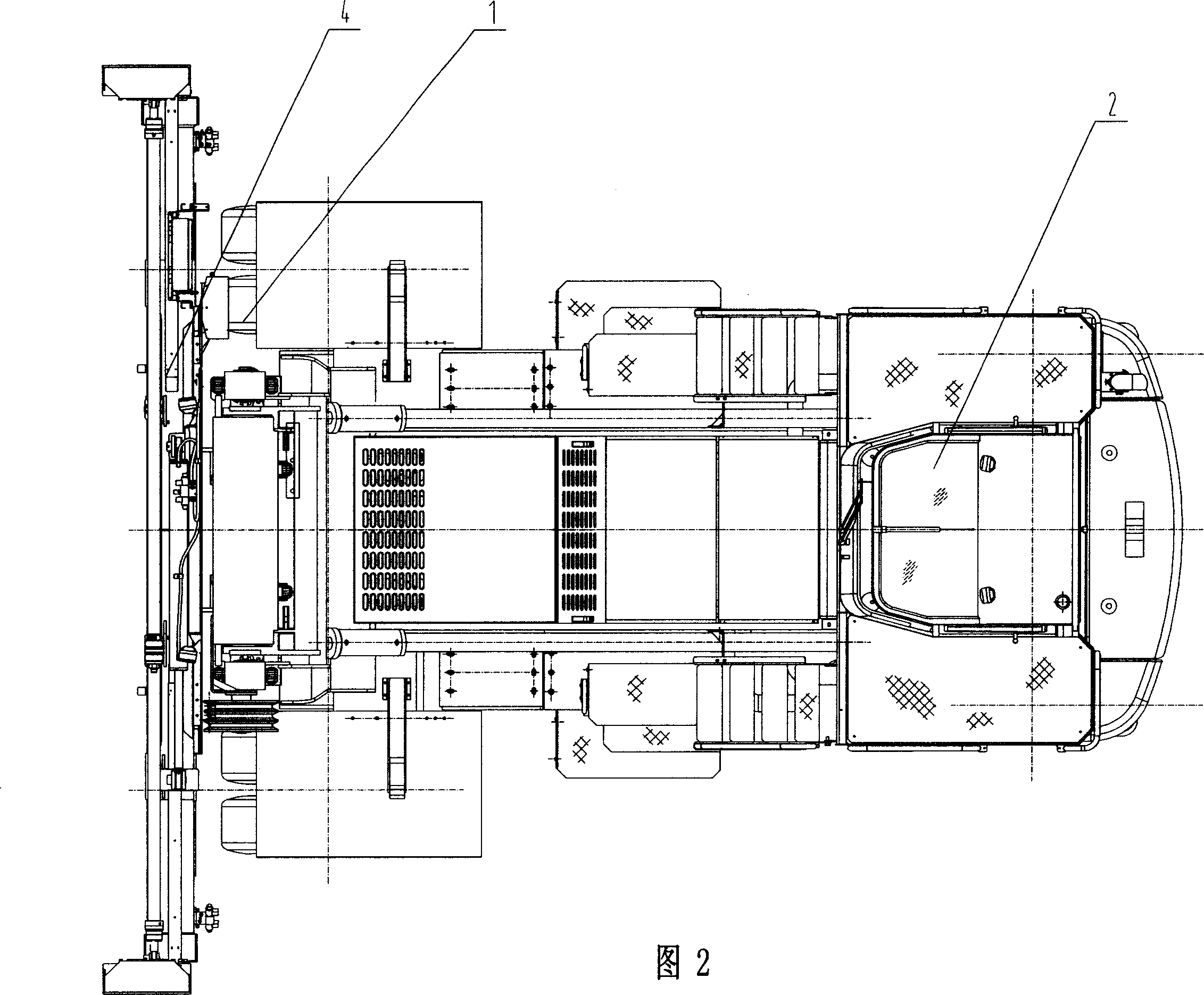
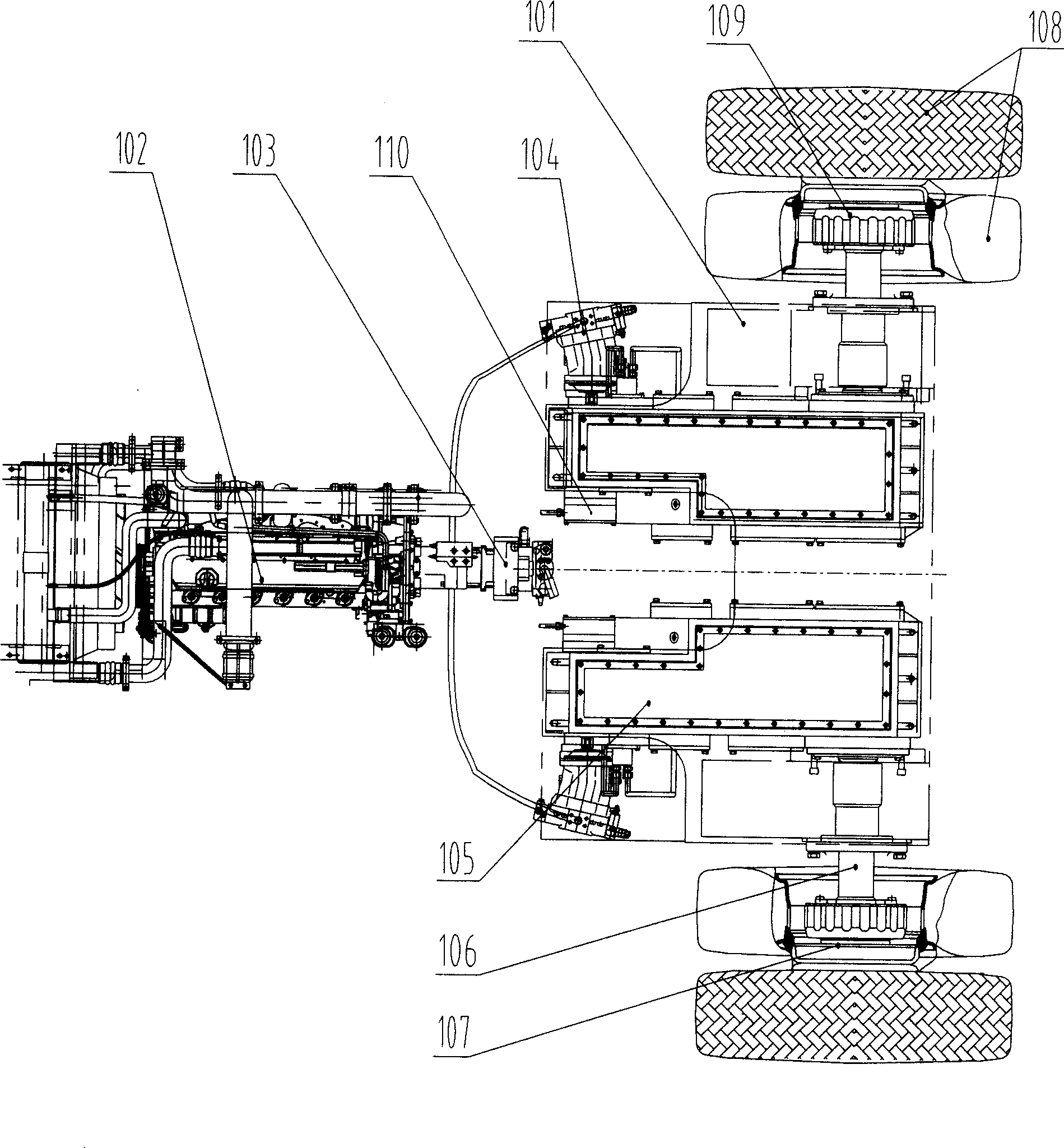
[0045] Figure 1, Figure 2 and image 3 As shown, the full hydraulic empty container stacker of the present invention comprises a traveling chassis 1, a driver's cab 2, a door frame 3 and a spreader 4, and the driver's cab 2 and the door frame 3 are installed on the walking chassis 1, and the spreader 4. Installed on the mast 3, the walking chassis 1 includes a chassis frame 101, an engine 102, a hydraulic pump 103, a hydraulic motor 104, a reducer 105, a half shaft 106, a wheel mechanism 107 and a tire assembly 108. The hydraulic pump 103 is connected to the output end of the engine 102. The hydraulic pump 103 is connected to two or more hydraulic motors 104 through pipelines. The output end of the hydraulic motor 104 is connected to the half shaft 106 through the reducer 105. The half shaft 106 passes The wheel edge mechanism 107 is ...


PUM


Abstract

The hydraulic empty container piling crane includes walking chassis, operator's cab, gantry and sling. The operator's cab and the gantry are installed on the walking chassis, and the sling is installed onto the gantry. The walking chassis includes chassis frame, engine, hydraulic pump, hydraulic motor, speed reducer, half shaft, wheel mechanism and tyre assembly. The hydraulic pump is connected to the output of the engine and connected via pipeline to at least two hydraulic motors, the hydraulic motor has output connected via the speed reducer to the half shaft, the half shaft is connected via the wheel mechanism to the tyre assembly, and the speed reducer is installed on the chassis frame. The present invention has high work efficiency, convenient operation, low use cost and other advantages.

Description

technical field [0001] The invention mainly relates to the field of container stacking and transshipment mechanical equipment, in particular to a fully hydraulic empty container stacker. Background technique [0002] The container stacker is a container handling and stacking device. In a sense, the container stacker belongs to walking lifting equipment. But there are following technical problems in the container stacker in the prior art: [0003] 1. During the working process of the empty container stacker, it needs to reciprocate within the working range and walk frequently. Its driving device basically adopts the form of hydraulic transmission. In the prior art, the hydrostatic traveling device of the stacker and the driving device of the traveling device include an engine, a gearbox, a transmission shaft, a drive axle and a tire assembly. The output shaft of the engine is connected with the gearbox, and the gearbox includes a hydraulic torque converter. The output shaft...

Claims


Application Information

Patent Timeline
Patent Type & Authority Applications(China)
IPC IPC(8): B66F9/07
Inventor 刘贞华李翠英易小刚廖荣华
Owner SANY HEAVY IND CO LTD (CN)
Why Eureka
Try Eureka