Metal Mg, Ca and Sr reducing apparatus

A metal magnesium and equipment technology, applied in the field of metal reduction equipment, can solve the problems of high labor intensity, long feeding and slagging time, and unsatisfactory reduction effect of feeding and slagging, so as to reduce labor intensity and simplify feeding and slagging. Operation, improve the effect of the restoration effect

Active Publication Date: 2007-01-03
张元友 +1
View PDF0 Cites 11 Cited by
  • Summary
  • Abstract
  • Description
  • Claims
  • Application Information

AI Technical Summary

Problems solved by technology

[0003] In order to solve the problems that the existing metal magnesium, calcium and strontium reduction equipment has long feeding and slagging time, high labor intensity, difficulty in mechanization or automation of feeding and slagging, and unsatisfactory reduction effect, the present invention provides a structure-improved, Reduction equipment for metal magnesium, calcium and strontium that can realize upper feeding and bottom slag discharge

Method used


Image

  • Metal Mg, Ca and Sr reducing apparatus
  • Metal Mg, Ca and Sr reducing apparatus
  • Metal Mg, Ca and Sr reducing apparatus

Examples


Embodiment Construction

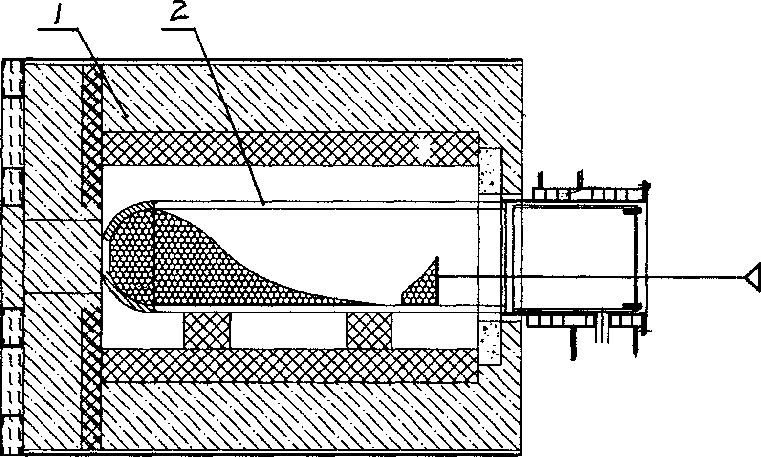
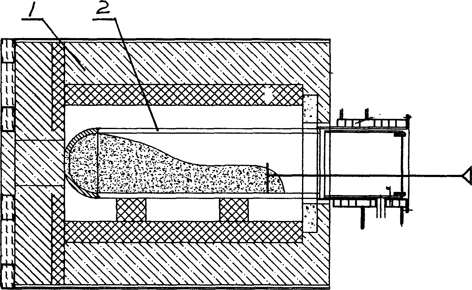
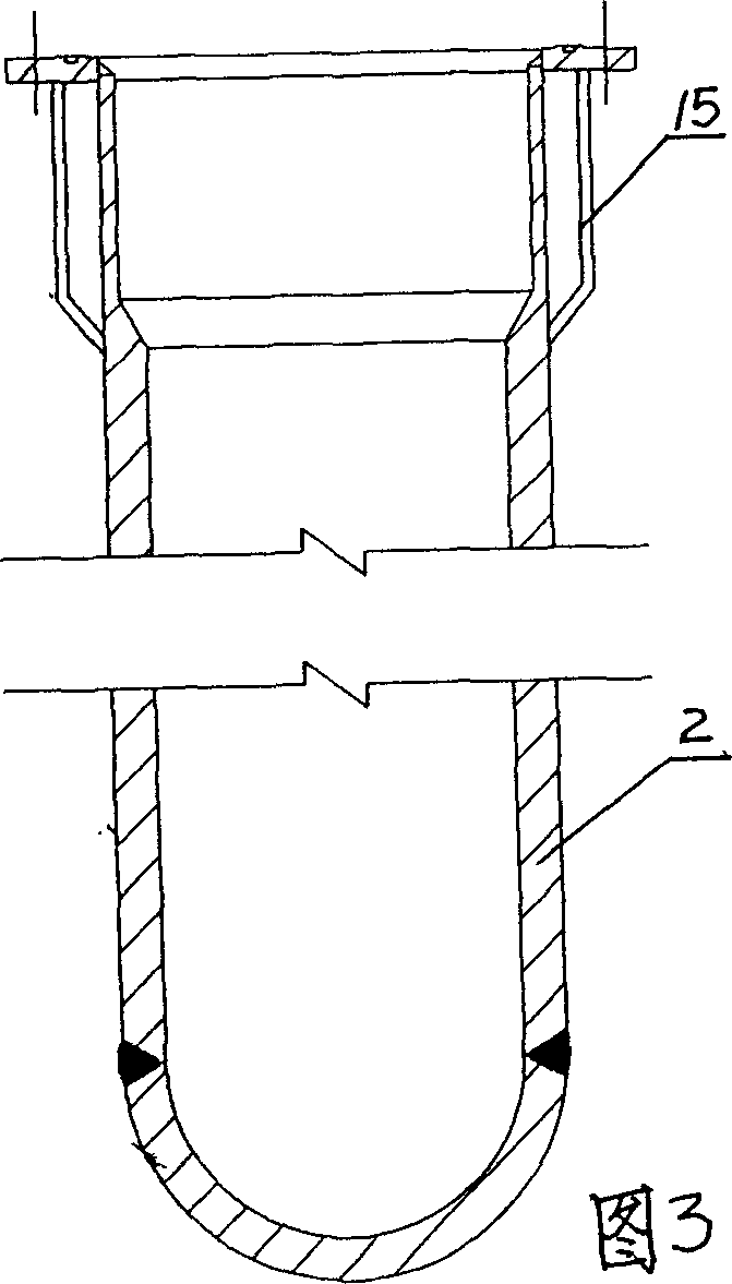
[0015] Metal magnesium, calcium, and strontium reduction equipment includes a reduction furnace 1 and a reduction tank 2 placed in the reduction furnace. The bottom of the reduction furnace 1 is provided with a support frame 3. The furnace 4 of the reduction furnace is a vertical furnace. The top of the furnace 4 is opened. There is an upper furnace mouth and a lower furnace mouth 5 at the bottom; a slag outlet 6 is opened at the bottom of the reduction tank, and a slag discharge pipe 7 is fixed at the bottom of the reduction tank, and the lower end of the slag discharge pipe is provided with a sealing cover 8 and a sealing cover 8 A sealing ring 9 is provided between the slag discharge pipe 7, and a water jacket 10 with inlet and outlet pipe ports is provided at the lower section of the slag discharge pipe. There is a flange connection between the sealing cover 8 and the slag discharge pipe 7, that is, a flange 11 is provided at the bottom of the slag discharge pipe, the seali...


PUM


Abstract

The present invention relates to metal reducing apparatus, and is especially one metal Mg, Ca and Sr reducing apparatus. The metal Mg, Ca and Sr reducing apparatus includes a reducing furnace, a reducing pot inside the reducing furnace, and a support in the bottom of the reducing furnace. The reducing furnace has vertical hearth with upper port in the top and lower port in the bottom; the reducing pot has slag tap in its bottom, slag pipe fixed to its bottom, sealing cover in the lower end of slag pipe, sealing ring between the sealing cover and the slag pipe, and water jacket set to the lower section of the slag pipe. The metal Mg, Ca and Sr reducing apparatus has greatly simplified slag tapping operation and raised material reducing effect.

Description

technical field [0001] The invention relates to metal reduction equipment, in particular to metal magnesium, calcium and strontium reduction equipment. Background technique [0002] The reduction process of metal magnesium, calcium and strontium is basically the same, and the reduction equipment used is also the same. Existing reduction equipment for metal magnesium, calcium, and strontium includes a reduction furnace and a reduction tank. The reduction furnace is directly placed on the ground and only has a furnace hole (horizontal furnace) on the side, and the reduction tank also has only one opening, which is used as a feeding material. The outlet is also used as the slag outlet (see attached figure 1 , 2 , 3). When working, the reduction tank is placed horizontally in the horizontal hearth of the reduction furnace. When feeding, it is necessary to manually push the raw materials into the reduction tank with a material shovel. And slag discharge time is long, labor in...

Claims


Application Information

Patent Timeline
IPC IPC(8): C22B5/02C22B26/20
Inventor 诸天柏张元友强立锋吴旭军王利顺
Owner 张元友
Why Eureka
Try Eureka