

Turbine cylinder casing thermal insulating method and thermal insulating cabin
A cylinder casing and steam turbine technology, applied to mechanical equipment, engine components, machines/engines, etc., can solve problems such as high cost of use, waste of the environment, and large waste, and achieve the effects of simple structure, good heat preservation effect, and convenient use
- Summary
- Abstract
- Description
- Claims
- Application Information
AI Technical Summary
Problems solved by technology
Method used
Image

Examples
Embodiment Construction
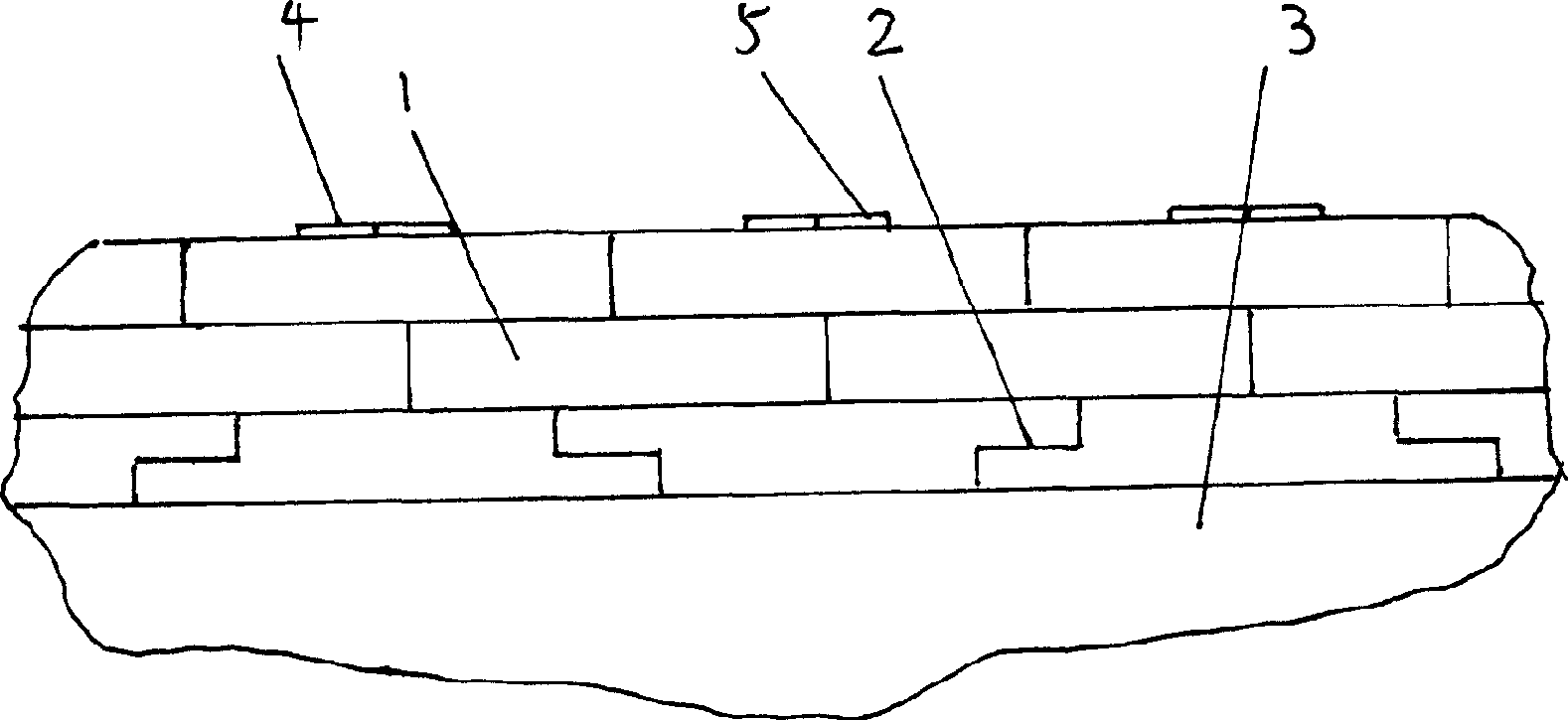
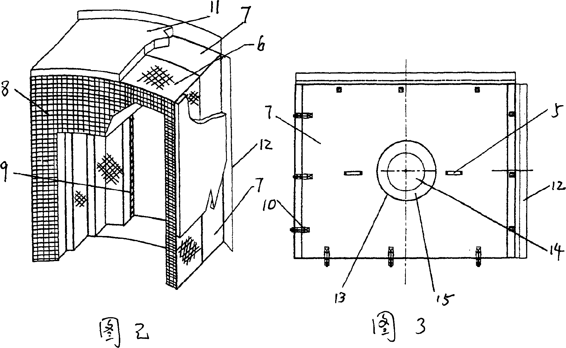
[0018] The present invention will be described in detail below in conjunction with the accompanying drawings: the thermal insulation method of the present invention, it is to make a certain number of block thermal insulation blankets first according to the surface shape and size of the cylinder shell, and lay a piece of thermal insulation blanket on the steam turbine shell. At least two thermal insulation layers are formed on the surface.
[0019] The formation of the thermal insulation layer is as follows: first laying a thermal insulation layer spliced by a block-shaped thermal insulation blanket on the surface of the steam turbine casing, and then splicing a layer of thermal insulation layer composed of the same or different block thermal insulation blankets on it, And when the upper insulation layer is spliced, the upper insulation blanket covers the connection gap formed between the two insulation blankets in the lower insulation layer, and the upper and lower layers for...
PUM
 Abstract
Description
Claims
Application Information