
Synchronous power takeoff

A technology for synchronizing ring gears and gears, applied in transmissions, gear transmissions, belts/chains/gears, etc., can solve the problems of inconvenient use, small transmission torque, poor workmanship, etc., and achieve convenient shifting operation and reliability High, light weight effect

Inactive Publication Date: 2007-01-03
威海西立电子股份有限公司
View PDF0 Cites 6 Cited by
  • Summary
  • Abstract
  • Description
  • Claims
  • Application Information

AI Technical Summary

Problems solved by technology

[0002] At present, the power take-off devices produced in China generally have shortcomings such as large volume, heavy weight, small transmission torque, and poor craftsmanship. The power take-off device invented by Muncie Company in the United States has patent numbers: 4573365 and 4573366. It is driven by gears and shifted gears. The operation is composed of two parts. The gear transmission part mainly includes: the shell formed by one-time casting of aluminum alloy material, the power take-off gear that is constantly meshed with the transmission gear of the vehicle gearbox (or transfer case), the intermediate shaft, and the combination of the internal spline structure Ring gear (joint sleeve), a pair of constant meshing driven gears (intermediate shaft gear and output shaft gear) and output shaft with external splines, two pairs of symmetrical mounting holes are processed on the housing, one pair of mounting holes is A power take-off gear, an intermediate shaft gear, an adapter sleeve (ring gear), and an intermediate shaft are installed; the other pair of mounting holes are installed with an output shaft gear and an output shaft; The casing, which cooperates with the casing of the gear transmission part to form a complete casing structure of the power take-off device, including shift trigger parts, shift forks and shift fork baffles and other components
The fork of the shift fork is located on the joint ring gear of the gear transmission part; when the shift trigger part rotates, the spring detent in the shift trigger part moves accordingly; thus the shift fork baffle rotates, and the shift fork baffle drives the shifter The fork also moves accordingly; the shift fork pushes the joint ring gear to move laterally, so that the power take-off gear and the intermediate shaft gear enter the meshing state or disengage. Its advantages are small size, light weight, high reliability, and large transmission torque, but its replacement The gear operation must be carried out when the power take-off gear is stationary, which brings a lot of inconvenience to the use

Method used


Image

  • Synchronous power takeoff

Examples


Embodiment Construction

[0011] The present invention will be further described below in conjunction with accompanying drawing:

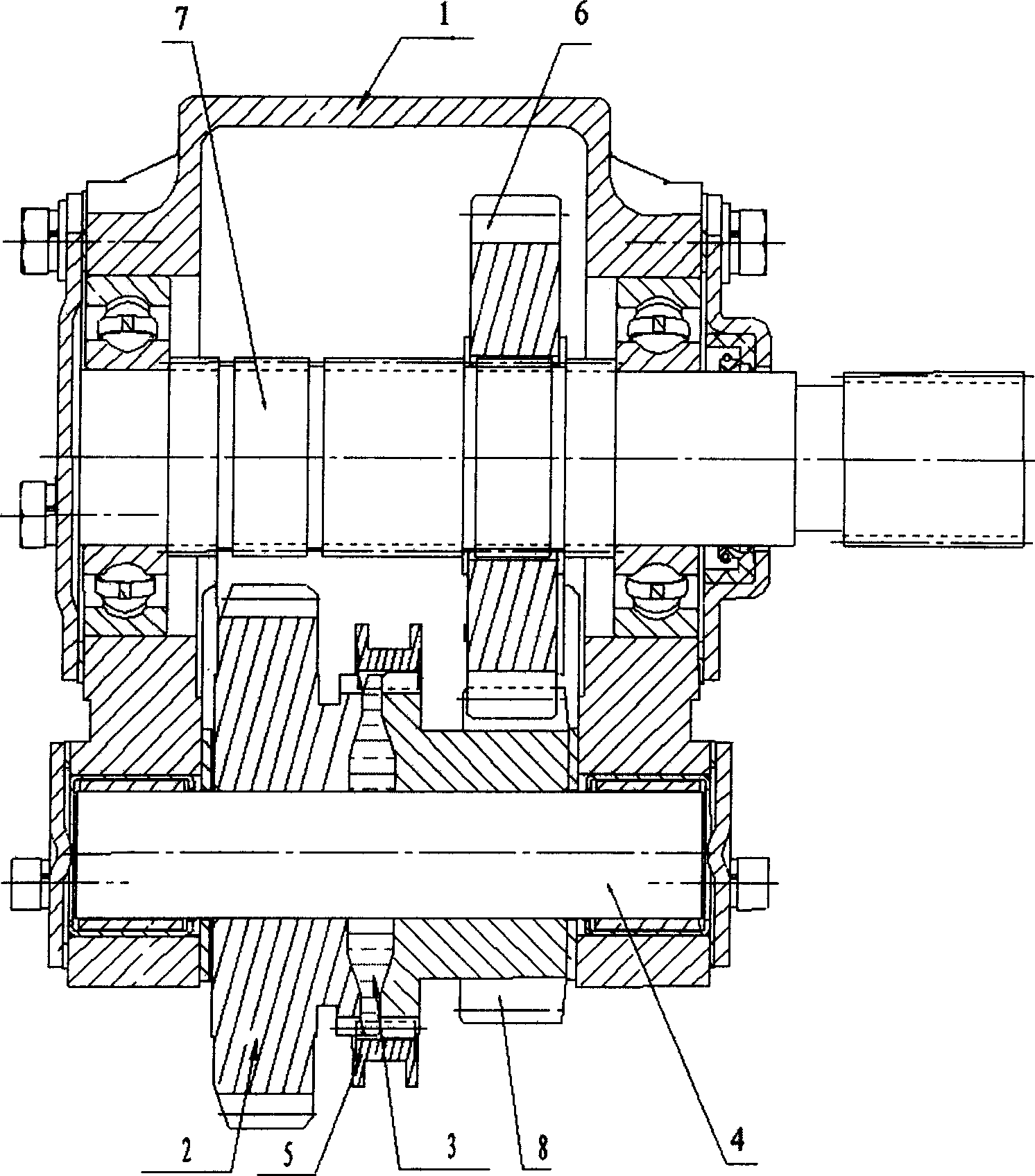
[0012] As shown in the drawings, a synchronous power take-off device is composed of two parts: gear transmission and gear shifting operation. The gear transmission part mainly includes: a housing 1 formed by one-time casting of aluminum alloy material. Inside the housing 1 is a Case (or transfer case) transmission gear, constant meshing power take-off gear 2, synchronous ring gear 3, intermediate shaft 4, combined ring gear (joint sleeve) with internal spline structure 5, a pair of constant meshing driven gears (intermediate shaft Gear 8 and output shaft gear 6) and the output shaft 7 with external splines, two pairs of symmetrical installation holes are processed on the housing 1, wherein, an intermediate shaft 4 is installed on a pair of installation holes, and an intermediate shaft 4 is installed on the intermediate shaft 4. Power gear 2, synchronous ring gear 3, interme...


PUM


Abstract

There is disclosed a synchronous power take-off means, which can realize to take out power from vehicle engines ( speed variators or transfercases ) for driving a generator, a gear pump, a water pump, a vacuum pump, an air compressor and the like. It consists of toothed gearing and gear shift operating parts. Between the power take-off gear disposed on the countershaft and the countershaft gear is mounted a synchronous gear ring, which is inserted in the countershaft gear.

Description

Technical field: [0001] The invention relates to a power transmission device, in particular to a synchronous power take-off device. Background technique: [0002] At present, the power take-off devices produced in China generally have shortcomings such as large volume, heavy weight, small transmission torque, and poor craftsmanship. The power take-off device invented by Muncie Company in the United States has patent numbers: 4573365 and 4573366. It is driven by gears and shifted gears. The operation is composed of two parts. The gear transmission part mainly includes: the shell formed by one-time casting of aluminum alloy material, the power take-off gear that is constantly meshed with the transmission gear of the vehicle gearbox (or transfer case), the intermediate shaft, and the combination of the internal spline structure Ring gear (joint sleeve), a pair of constant meshing driven gears (intermediate shaft gear and output shaft gear) and output shaft with external splines...

Claims


Application Information

Patent Timeline
Patent Type & Authority Applications(China)
IPC IPC(8): F16H1/06
Inventor 连立民
Owner 威海西立电子股份有限公司
Learn More