
Display panel

A technology of display panel and liquid crystal display panel, applied in static indicators, instruments, etc., can solve the problem of increasing power consumption, and achieve the effect of reducing excitation voltage and power consumption

Active Publication Date: 2007-01-03
NOVATEK MICROELECTRONICS CORP
View PDF0 Cites 5 Cited by
  • Summary
  • Abstract
  • Description
  • Claims
  • Application Information

AI Technical Summary

Problems solved by technology

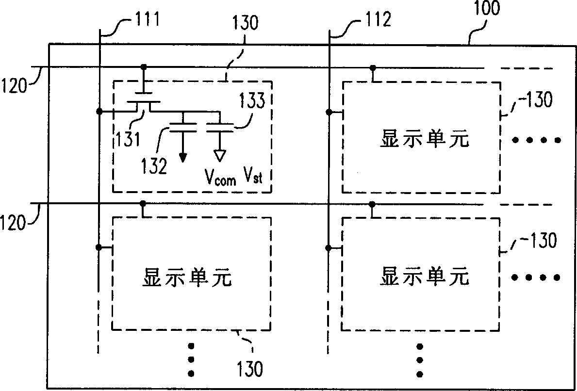
[0004] With the increase of panel size and resolution, or because of wide viewing angle technologies such as in-plane switching (In-plane Switching, IPS) or multi-domain vertical alignment (Multi-domain Vertically Alignment, MVA), higher voltage drive is required , all these reasons lead to greater power consumption

Method used


Image

  • Display panel
  • Display panel
  • Display panel

Examples


Embodiment Construction

[0036] In the following, a liquid crystal display panel will be taken as an example to illustrate the present invention conveniently. Those skilled in the art can infer various display panels according to the spirit of the present invention and the teachings and revelations of the following embodiments. Figure 4 An embodiment of a display panel is described according to the present invention. Please refer to Figure 4 , in order to illustrate this embodiment more clearly, the peripheral circuits (eg source driver and gate driver) coupled to the display panel 400 are not shown. Here it is assumed that the display panel 400 has X data lines DL 0 ~DL X-1 , Y scan lines SL 0 ~SL Y-1 And X*Y display units SP 0,0 ~ SP X-1,Y-1 . Among them, SP i,j Indicates the display unit of column i and row j. The gate driver will pass the scan line SL 0 ~SL Y The corresponding display units are turned on row by row. In line with the timing of the gate driver, the source driver also ...


PUM


Abstract

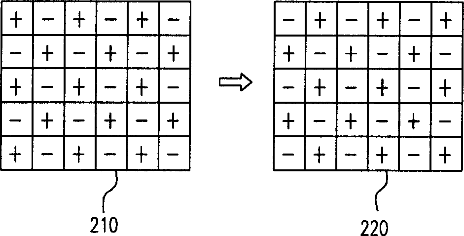
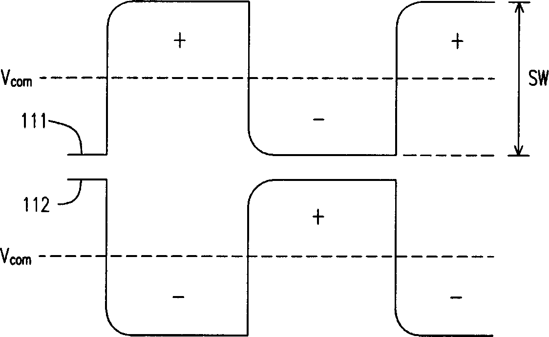
This invention discloses a kind of display faceplate, liking the display element in the same location of the odd number and even number row in the display element array of the display faceplate to different data wire, to make each date wire of the display faceplate keep unitary polarity in most time. Therefore, it can cut down the driving voltage of the data wire in display faceplate, achieving the province purpose by cutting down the power consumption of the faceplate.

Description

technical field [0001] The present invention relates to a display device, and in particular to a display panel capable of reducing the polarity inversion frequency of data lines. Background technique [0002] In recent years, image display technology has made considerable progress and development. A large number of conventional cathode ray display applications have been replaced by flat panel displays. Common flat panel displays include thin film transistor liquid crystal display (TFT-LCD), low temperature polysilicon liquid crystal display (LTPS LCD) and organic electroluminescence display (OLED). Recently, low-temperature polysilicon (LTPS) and amorphous silicon (a-Si) thin-film transistor liquid crystal displays (TFT-LCDs) have gradually become the mainstream of flat-panel displays in the market. Various liquid crystal displays can be found in notebook computers, monitors, audio-visual devices, televisions or mobile phones. [0003] figure 1 It is to illustrate a know...

Claims


Application Information

Patent Timeline
Patent Type & Authority Applications(China)
IPC IPC(8): G09G3/20G09G3/36G02F1/133
Inventor 林哲立陈章三
Owner NOVATEK MICROELECTRONICS CORP
Learn More