
Explosion circuit breaker

A circuit breaker, a new type of technology, applied in the direction of explosive switches, circuits, electrical components, etc., can solve the problems of low long-term working current, small breaking current, slow breaking speed, etc., and achieve high breaking reliability and high rated breaking current , The effect of fast breaking speed

Inactive Publication Date: 2007-01-03
INST OF PLASMA PHYSICS CHINESE ACAD OF SCI
View PDF0 Cites 6 Cited by
  • Summary
  • Abstract
  • Description
  • Claims
  • Application Information

AI Technical Summary

Problems solved by technology

[0002] The existing traditional mechanical switch is to make the moving contact through a certain stroke through the connecting rod transmission mechanism to realize the contact closure and the energy storage spring to complete the energy storage, so as to prepare for the breaking of the switch. The spring can be released quickly to make the switch moving contact and the static contact quickly separate to realize the switch breaking. This kind of mechanical switch using spring as the driving device has small breaking current, slow breaking speed and relatively low reliability.
Although the existing bridge-type explosive switch has a simple structure and fast breaking speed, its biggest disadvantage is that the long-term working current is small. As the magnet quench backup protection switch in the EAST tokamak device, the switch must have a fast breaking speed and can be used for a long time. With the characteristics of carrying and breaking large currents and high breaking reliability, the existing mechanical switches cannot meet the requirements, but the invented new explosive circuit breaker equipment can meet the above requirements

Method used


Image

  • Explosion circuit breaker
  • Explosion circuit breaker

Examples


Embodiment Construction

[0017] The specific use of the present invention will be described in further detail below in conjunction with the accompanying drawings.

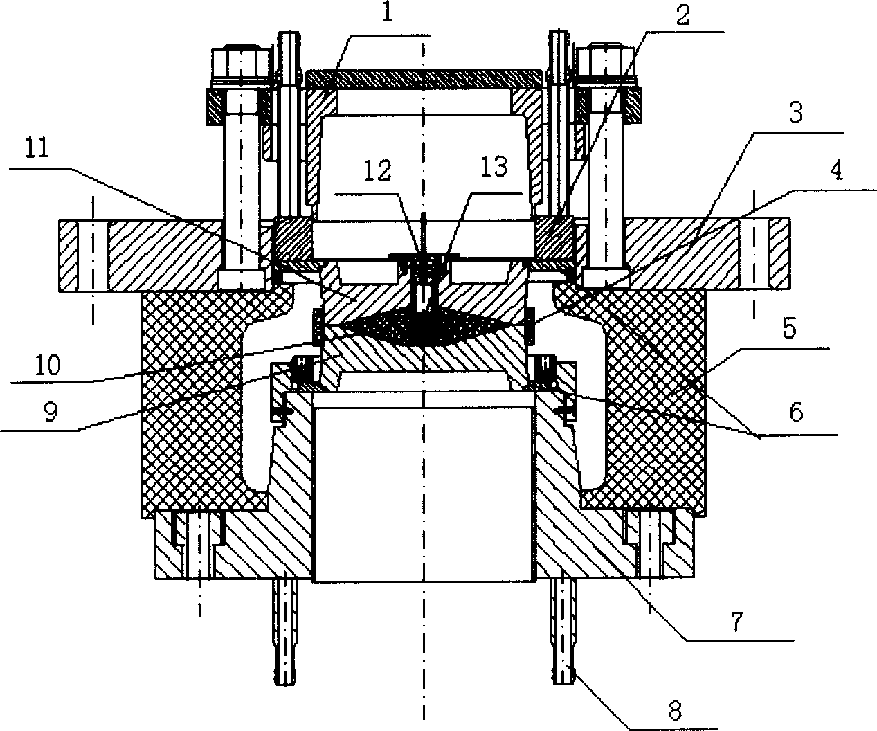
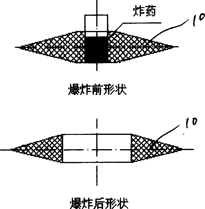
[0018] as attached figure 1 As shown in the new explosive circuit breaker, the upper disc 3, the chassis 7, the insulating cylinder 5 and the bolts form the switch main body; the contact system is composed of the upper contact 11, the lower contact 9, the upper and lower conductive rings 6, and the insulating ring 4 are set outside the upper and lower contacts; the water cooling ring 2, steel bushing 1 and bolts form a clamping mechanism, and the important driving part is composed of a detonator 12, an explosive 13 and an insulating block 10 between the upper and lower contacts. Block 10 in shape as attached figure 2 Shuttle wheel shape shown, wherein the detonator 12 and the explosive 13 are located in the through hole in the middle of the insulating block 10 .

[0019] The chassis 7 is composed of a cylinder and a ring platform on the...


PUM


Abstract

The invention discloses a new type explosion breaker. The insulating barrel is installed on the underpan and on the barrel there is a upper disc with a hole in the center. There is a hole in the center of the underpan. The lower conducting ring is set around the hole. The lower conducting ring is set along the inner edge of the insulating barrel. There are a upper and a lower contactor between the upper and the lower conducting ring. Between two contactors is a insulating block in which sets detonator. The water-cooling ring is on the upper conducting ring. The bush presses on the water-cooling ring. The bush and the upper disc are connected. The structure is novel; the rated drop-out current is strong; the drop-out speed is fast; the drop-out reliability is nice. The new type explosion breaker is not only applied in the nuclear fusion device as the reserved switch, but in the electric system it has broad application prospect as the protective switch.

Description

technical field [0001] The invention belongs to a novel high-power mechanical switchgear, in particular to a novel explosive circuit breaker. Background technique [0002] The existing traditional mechanical switch is to make the moving contact through a certain stroke through the connecting rod transmission mechanism to realize the contact closure and the energy storage spring to complete the energy storage, so as to prepare for the switch breaking. The spring can be quickly released to quickly separate the moving contact and the static contact of the switch to realize the switch breaking. This kind of mechanical switch using the spring as the driving device has a small breaking current, slow breaking speed and relatively low reliability. Although the existing bridge-type explosive switch has a simple structure and fast breaking speed, its biggest disadvantage is that the long-term working current is small. As the magnet quench backup protection switch in the EAST tokamak d...

Claims


Application Information

Patent Timeline
Patent Type & Authority Applications(China)
IPC IPC(8): H01H39/00
Inventor 宋执权傅鹏吴友国吴义兵
Owner INST OF PLASMA PHYSICS CHINESE ACAD OF SCI
Learn More