Lens driver and process for manufacturing the same

A lens driving device and lens technology, which is applied in electromechanical devices, installations, instruments, etc., can solve the problems of focus deviation between the lens and the imaging element, and cannot provide a stable quality lens driving device, so as to achieve miniaturization and avoid interference.

Inactive Publication Date: 2007-01-03
SANKYO SEIKI MFG CO LTD
View PDF0 Cites 20 Cited by
  • Summary
  • Abstract
  • Description
  • Claims
  • Application Information

AI Technical Summary

Problems solved by technology

Furthermore, even if a CCD camera is used for high-precision focusing before installing the imaging element, when the imaging element is installed later, the focus of the lens and the imaging element will be deviated due to the size error of the imaging element or the installation error of the imaging element. , so there is a problem of not being able to provide a lens driving device with stable quality

Method used


Image

  • Lens driver and process for manufacturing the same
  • Lens driver and process for manufacturing the same
  • Lens driver and process for manufacturing the same

Examples


Embodiment Construction

[0015] Embodiments of the lens driving device of the present invention will be described below with reference to the drawings. Furthermore, a method of manufacturing a lens driving device and a portable device with a camera will also be described together. The structure of each embodiment is suitable for installation as a camera portion of a portable device such as a mobile phone, but it can also be installed in other portable devices such as a PDA (Personal Digital Assistant).

[0016] (the whole frame)

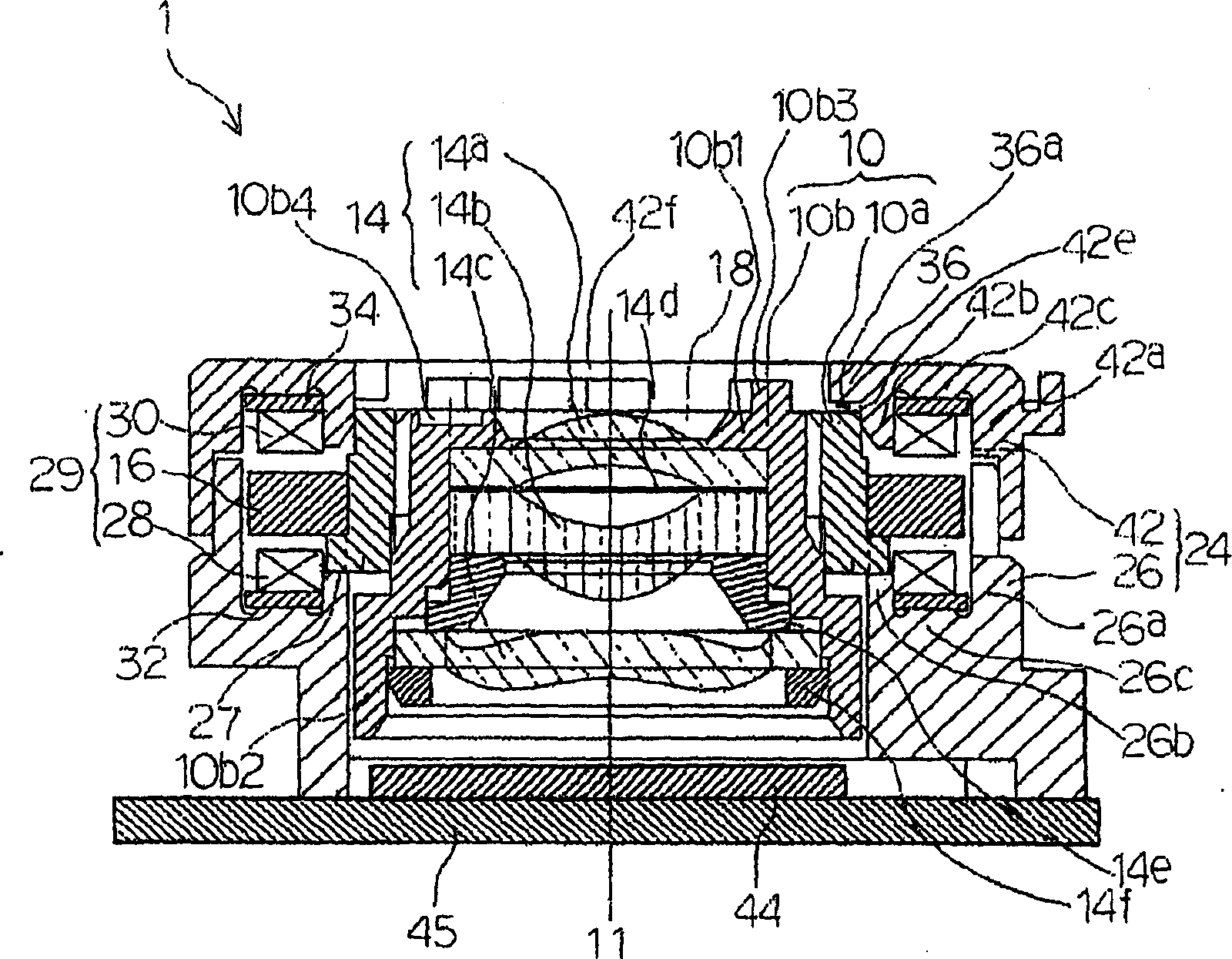
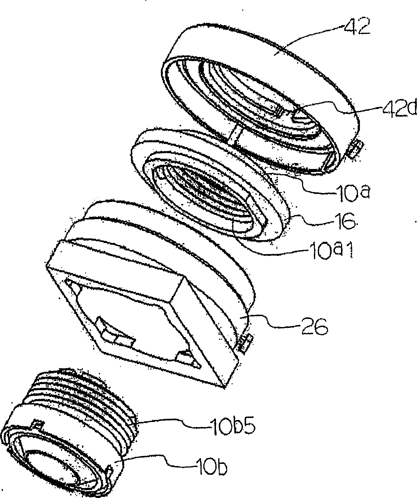
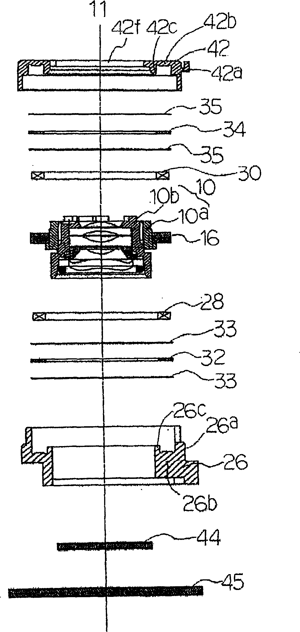
[0017] figure 1 It is a sectional view showing the lens driving device of the present invention. figure 2 yes figure 1 An exploded perspective view of the lens actuator shown.

[0018] Such as figure 1 or figure 2 As shown, the lens driving device 1 mainly includes: a moving lens body 10 that holds the imaging lens 14 of the camera; a magnetic drive member 29 that moves the moving lens body 10 linearly along the optical axis 11 direction of the lens 14; accommodates ...


PUM


Abstract

A lens driver (1) comprising a moving lens body (10) consisting of a lens-barrel (10b) provided with a lens (14) and a lens-barrel holder (10a) for supporting the lens-barrel (10b) so as to be movable in the direction of the optical axis (11). The lens-barrel holder (10a) has a driving magnet (16) and a case body (24) for supporting the moving lens body (10) so as to be movable in the direction of the optical axis (11) encases first and second driving coils and has an end face (27) of an inner tubular section (26b) and a projecting edge (36) of an inner tubular section (42b) that regulate the moving range of the lens-barrel holder (10a) in the direction of the optical axis (11). The moving lens body (10) is moved by a magnetic attracting force or repelling force of the driving magnet (16) and the first and second driving coils.

Description

technical field [0001] The present invention relates to a driving device for a lens used in a relatively small camera such as a mobile phone with a camera and a manufacturing method thereof. Background technique [0002] For a mobile phone equipped with a camera, in many cases, the mobile phone is held in one hand to take pictures of one's own face or other objects close to the location. Therefore, most imaging lens systems used in such cameras have a close-up imaging function. When such an imaging lens system having a close-range imaging function is used, the lens position when performing normal imaging is different from the lens position when performing close-range imaging, that is, low-magnification imaging. That is, the lens position during close-range imaging is slightly closer to the subject side by a certain distance than the lens position during normal imaging. [0003] Therefore, in this imaging lens system, there is a magnetic drive mechanism that moves the lens ...

Claims


Application Information

Patent Timeline
Patent Type & Authority Applications(China)
IPC IPC(8): G02B7/04G02B7/08G02B13/00H02K33/00
CPCG02B13/006G02B7/08
Inventor 小酒井正浩米山秀和大槻登
Owner SANKYO SEIKI MFG CO LTD
Why Eureka
Try Eureka