Method for detecting oil field fluid-channeling channel

A detection method and channeling technology, which are applied in the fields of production of fluids, earth-moving drilling, wellbore/well components, etc., can solve the problems of not establishing an effective method for channeling channel detection and diagnosis, fuzzy evaluation and testing of static geological parameters. Accuracy, resolution, and detection of formation depth are limited, etc., to achieve the effect of strong operability and good technical support

Inactive Publication Date: 2007-01-10
CHINA UNIV OF PETROLEUM (BEIJING)
View PDF0 Cites 21 Cited by
  • Summary
  • Abstract
  • Description
  • Claims
  • Application Information

AI Technical Summary

Problems solved by technology

[0003] At present, the attention and research on cross-flow channels have attracted extensive attention in various oil companies, but the research work carried out by various oil companies in this field focuses on the testing in the wellbore. The accuracy, resolution and accuracy of the testing The formation depth is limited, and there is no breakthrough progress; on the other hand, the fuzzy evaluation of static geological parameters and the qualitative judgment

Method used


Image

  • Method for detecting oil field fluid-channeling channel
  • Method for detecting oil field fluid-channeling channel
  • Method for detecting oil field fluid-channeling channel

Examples


Embodiment 1

[0023] A.+3-9.2 well group

[0024] The following takes oil well 1-8.4 as an example to illustrate the drawing process of oil well water cut characteristic curve.

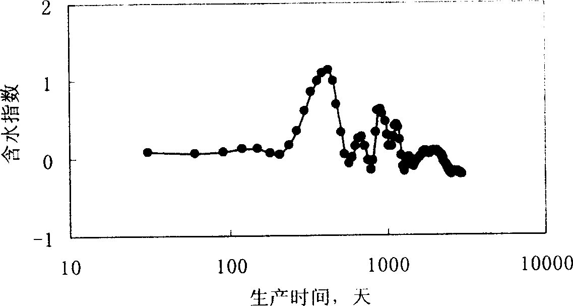
[0025] Select the accumulated water and oil production from the monthly production report of the 1-8.4 oil well, calculate the production time T from the time the oil well is put into production, and the cumulative production at each time point (i represents the time point, i+1 represents the next time point) Water is divided by cumulative oil production to obtain cumulative water-oil ratio CWOR, and then according to the formula log(CWOR i+1 / CWOR i ) / log(T i+1 / T i ), "It can also be expressed as (logCWOR i+1 -logCWOR i ) / (logT i+1 -logT i )” to obtain the water content index, and draw the water content index and production time on the semi-logarithmic coordinate graph to obtain the water content index characteristic curve (see figure 1 ).

[0026] +1-8.4 Wells (see figure 2 ) and 3-9.2 oil well (see ...

Embodiment 2

[0031] B.5-9.2 Well Group

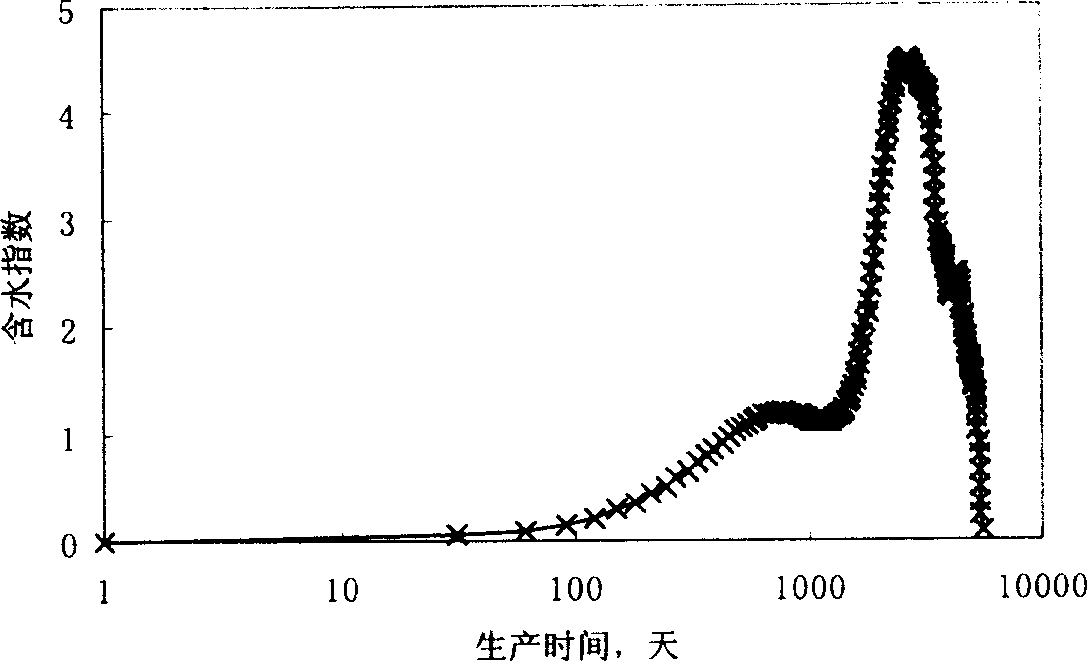
[0032] For the 5-9.2 water well in Jilin Fuyu Oilfield, the water cut index characteristic curve of the corresponding oil well +3-9.4 is obviously concave on the whole (see Figure 4 ), according to the detection method of the present invention (the change shape of the water cut index characteristic curve of the oil well whose channeling channel is a fracture type is concave), the conclusion is that there is a fractured channeling channel in the oil well +3-9.4.

[0033] The channeling channel is checked by injecting different blocking agents (particle type, gel type).

[0034] Well 5-9.2 injected a total of 150.0 cubic meters and used 1960.0 kg of body-expanding particles. The injection pressure rose from 4.3Mpa to 6.0Mpa, and the pressure increase was normal. It was explained on site that there were fracture-type channeling channels in the well. The channel type of channeling is consistent with the interpretation results.

Embodiment 3

[0036] C.+7-0.2 well

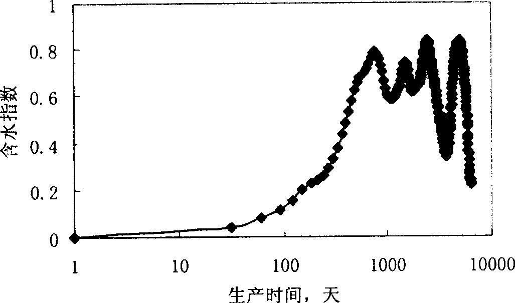
[0037] The water cut index characteristic curve of the well is shown in Figure 5 . From Figure 5 It can be seen that its characteristic curve is concave, and according to the detection method of the present invention, the channeling channel type of this well is a fracture type (see Figure 5 ).

[0038] The well was once monitored with tracers. The monitoring and interpretation results show that there are fracture-type channeling channels, which is consistent with the interpretation results of the water-cut characteristic index curve.


PUM


Abstract

The invention provides a method for detecting oil field fluid channeling, utilizing water-containing index characteristic curve to measure the performance of production well in the oil field, concretely speaking: collecting oil output and fluid output of the oil well from starting to test at regular intervals; calculating water-oil ratio or water ratio of the oil well at regular intervals; finding first-order derivative of common logarithm of the water-oil ratio or water ratio to common logarithm of time, namely the water-containing index; using the water-containing index as vertical coordinate and producing time as horizontal coordinate to make its half-logarithm relation curve and obtaining the water- containing index characteristic curve; detecting the type of the fluid channeling according to the shape of the water-containing index characteristic curve. And the method has objectivity and strong operability.

Description

technical field [0001] The invention provides a method for detecting the type of channeling channels in water flooding oilfields, especially a method for detecting the types of channeling channels based on changes in production dynamic characteristics of high water-cut oilfields, providing technical support for controlling water and stabilizing oil in oilfields . Background technique [0002] Oil reservoirs (oil fields) are exploited in the form of oil wells. At present, water wells (water injection wells) are developed near most oil wells. By injecting water from the water wells to the oil wells, the crude oil (also called water injection wells) is pushed out by water displacement. oil displacement), the oil fields produced by this method have gradually become water-bearing oil fields, in which the channeling channels in the oil wells are mainly formed by the long-term erosion of the injected water on the high-permeability strips (fractures, pores) in the oil layer. The ch...

Claims


Application Information

Patent Timeline
IPC IPC(8): E21B49/00E21B49/08E21B43/20
Inventor 姜汉桥陈民锋赵传峰张贤松王佩华张志英
Owner CHINA UNIV OF PETROLEUM (BEIJING)
Why Eureka
Try Eureka