
Automatic fluorescent inspecting system

An automatic fluorescence and detection system technology, applied in the field of detection systems, can solve problems such as non-enhancement, and achieve the effect of speeding up the operation process and reducing the operation time.

Inactive Publication Date: 2007-01-17
赵世光 +1
View PDF0 Cites 5 Cited by
  • Summary
  • Abstract
  • Description
  • Claims
  • Application Information

AI Technical Summary

Problems solved by technology

There is currently no automated fluorescent detection system dedicated to resecting tumors, especially non-enhancing and low-grade gliomas

Method used


Image

  • Automatic fluorescent inspecting system
  • Automatic fluorescent inspecting system

Examples


Embodiment Construction

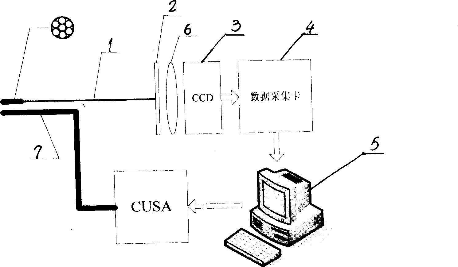
[0009] After the optical fiber bundle 1 of the present invention collects the optical signal, the background light is filtered out by the filter plate 2, and then irradiated to the surface of the CCD imaging system 3 after passing through the lens 6; the CCD imaging system 3 replaces the optical signal into one capable of reflecting light intensity information The electrical signal; after the electrical signal is filtered and amplified, the data acquisition card 4 carries out data acquisition and conversion and is sent to the computer 5; the present invention selects the optical fiber numerical aperture well, and needs to obtain the light intensity of the signal light through calculation and related experiments The numerical aperture of the optical fiber is selected according to the requirements of the characteristics and the measurement accuracy of the system. If the aperture is too large, the positioning accuracy of the system will decrease, and if the aperture is too small, ...


PUM


Abstract

An automatic fluorescent detection system for cutting out tumor is composed of optical fiber cluster, optical filter, lens, CCD imaging system, data acquisition card, computer and CUSA controlled ultrasonic suction probe.

Description

Technical field: [0001] The invention relates to a detection system for brain glioma operation equipment. technical background: [0002] Glioma is a common disease in the field of neurosurgery. Due to the unclear boundary between tumor tissue and normal tissue, it is difficult to completely remove it by surgery. Glioma has the characteristics of progressive development and aggressive growth, and belongs to the category of malignant tumors. Surgical resection is very necessary in the treatment of malignant glioma, and the most important method is to remove the tumor as much as possible. However, there is no proper method to judge the tumor tissue and the surrounding brain tissue, and there is no objective standard to judge the extent of tumor resection, and often the tumor resection depends entirely on the judgment of the surgeon, especially on the experience of the surgeon. In 1948, Moore GE first proposed the method of using fluorescent labeling to remove tumors. However...

Claims


Application Information

Patent Timeline
Patent Type & Authority Applications(China)
IPC IPC(8): A61B19/00A61B5/00A61B18/00A61B17/00G01N21/00
Inventor 赵世光张健
Owner 赵世光
Learn More