Ion beam etching method and ion beam etching apparatus

A technology of ion beam etching and ion beam, which is applied in the direction of ion beam tube, magnetic recording, nanotechnology, etc., can solve the problems of uneven radial distribution of ion beam intensity and reduced efficiency of ion beam extraction, and achieve the purpose of improving extraction efficiency and diameter Uniform distribution and suppression of distortion

Inactive Publication Date: 2007-01-17
TDK CORPARATION
View PDF1 Cites 10 Cited by
  • Summary
  • Abstract
  • Description
  • Claims
  • Application Information

AI Technical Summary

Problems solved by technology

If the ion beam is extracted with this extraction electrode, then the following problems are produced: (1) because the outgoing direction of the ion beam does not become a certain direction, the radial distribution of the ion beam intensity becomes inhomogeneous; (2) the extraction efficiency of the ion beam reduce

Method used


Image

  • Ion beam etching method and ion beam etching apparatus
  • Ion beam etching method and ion beam etching apparatus
  • Ion beam etching method and ion beam etching apparatus

Examples


Embodiment Construction

[0025] Hereinafter, embodiments of the present invention will be described in detail with reference to the drawings. In addition, in the description of the drawings, the same reference numerals are used for the same or equivalent elements, and repeated descriptions are omitted.

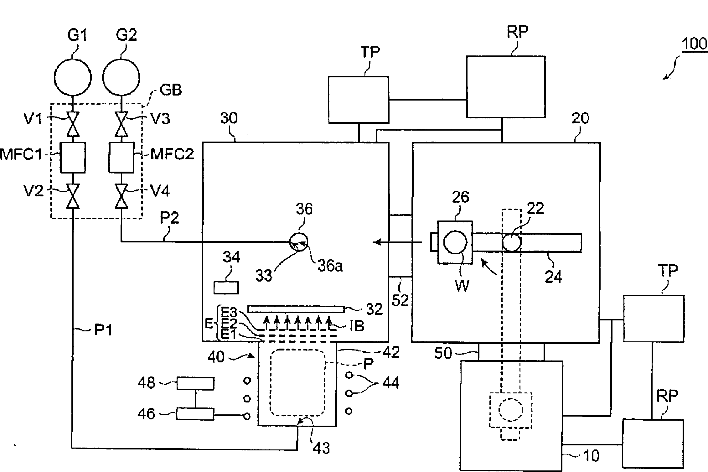
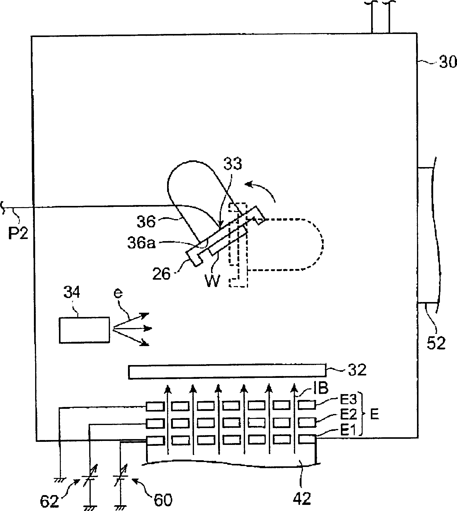
[0026] figure 1 It is a schematic diagram showing the configuration of an ion beam etching apparatus (also referred to as an ion milling apparatus) according to the embodiment. figure 2 yes means figure 1 A schematic diagram of the configuration of the main parts of the ion beam etching apparatus shown in .

[0027] figure 1 The ion beam etching apparatus 100 shown in is suitably used in the manufacture of thin-film magnetic heads for HDDs (for example, GMR magnetic heads, TMR magnetic heads). In particular, it can be favorably applied to the processing of the ABS surface and the chamfered portion which define the flying height of the thin-film magnetic head. The ion beam etching apparatus 100 i...


PUM


Abstract

The ion beam etching method according to the embodiment includes a cooling step (S52) of cooling the extraction electrode (E) with an inert gas, and etching the workpiece (W) with the ion beam (IB) extracted from the extraction electrode (E). Etching process (S54).

Description

technical field [0001] The invention relates to an ion beam etching method and an ion beam etching device. Background technique [0002] There is known an ion beam etching method for etching a workpiece by irradiating an ion beam to the surface of the workpiece (see, for example, JP 2002-510428 A). This ion beam is obtained by extracting the ions in the plasma generated in the discharge vessel of the ion source with the extraction electrode. [0003] However, if a voltage is applied to the extraction electrode to extract the ion beam, the extraction electrode may be deformed by the heat of the plasma generated in the discharge vessel. For example, when an extraction electrode composed of three metal plates is used, since the heat supplied from the plasma to each metal plate is different, the amount of deformation of each metal plate is different. Therefore, the center positions of the lead-out holes formed on the respective metal plates are shifted from each other. If the...

Claims


Application Information

Patent Timeline
Patent Type & Authority Applications(China)
IPC IPC(8): C23F4/00H01J27/02H01J37/08
CPCB82Y10/00G11B5/3163G11B5/3103H01J2237/3174H01J37/08G11B5/3909
Inventor 堀田哲广久保田尚树
Owner TDK CORPARATION
Why Eureka
Try Eureka