
Non-friction air-compression and power generator

A generation device, frictionless technology, applied in the direction of variable displacement engine, reciprocating piston engine, machine/engine, etc., can solve the problems of material intolerance, oil and gas leakage, material wear and so on

Inactive Publication Date: 2007-01-17
林耀章
View PDF0 Cites 1 Cited by
  • Summary
  • Abstract
  • Description
  • Claims
  • Application Information

AI Technical Summary

Problems solved by technology

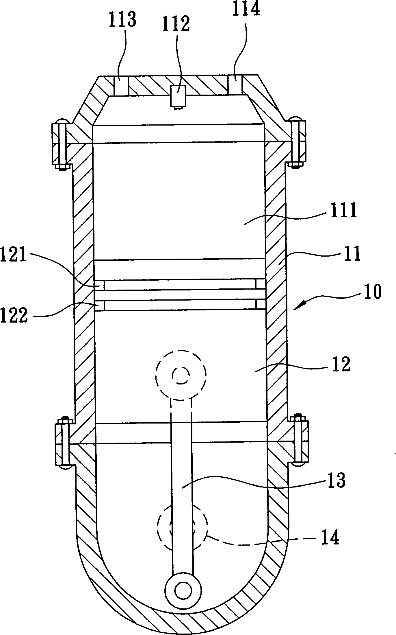
[0003] The above-mentioned power machine 10 is a mechanism that has been used for a long time and can indeed generate power, but there are still many technical problems in use that need to be solved urgently. Generally, although the gas ring 121 and the oil ring 122 are made of wear-resistant materials, they are Long-term contact and friction with the inner wall of the piston air chamber 111 will still cause material wear, causing oil and gas to leak out and reduce the output horsepower. The power machine 10 generates high heat, and the cooling problem has always been the focus of the industry, because once the temperature exceeds the range that the material can withstand, the piston element 12 may shrink due to overheating and expansion, and the entire power machine 10 will be scrapped and cannot be used. The industry has researched and developed solutions to the frictional resistance and high heat problems of the piston element 12, but the method is nothing more than changing the material, that is, using ceramics or artificial diamond powder ... and other materials with hard and high temperature resistance properties to solve the problem, although This method can slightly improve the friction resistance between parts and the problem of high heat generation, but these materials are too brittle and not resistant to impact, which will cause hidden troubles in use. Therefore, how to overcome the friction resistance and high heat problems of the piston element 12, It has always been a subject that the industry has worked hard to develop and solve

Method used


Image

  • Non-friction air-compression and power generator
  • Non-friction air-compression and power generator
  • Non-friction air-compression and power generator

Examples


Embodiment Construction

[0020] The foregoing and other technical contents, features and effects of the present invention will be clearly presented in the following detailed descriptions of several preferred embodiments with reference to the drawings.

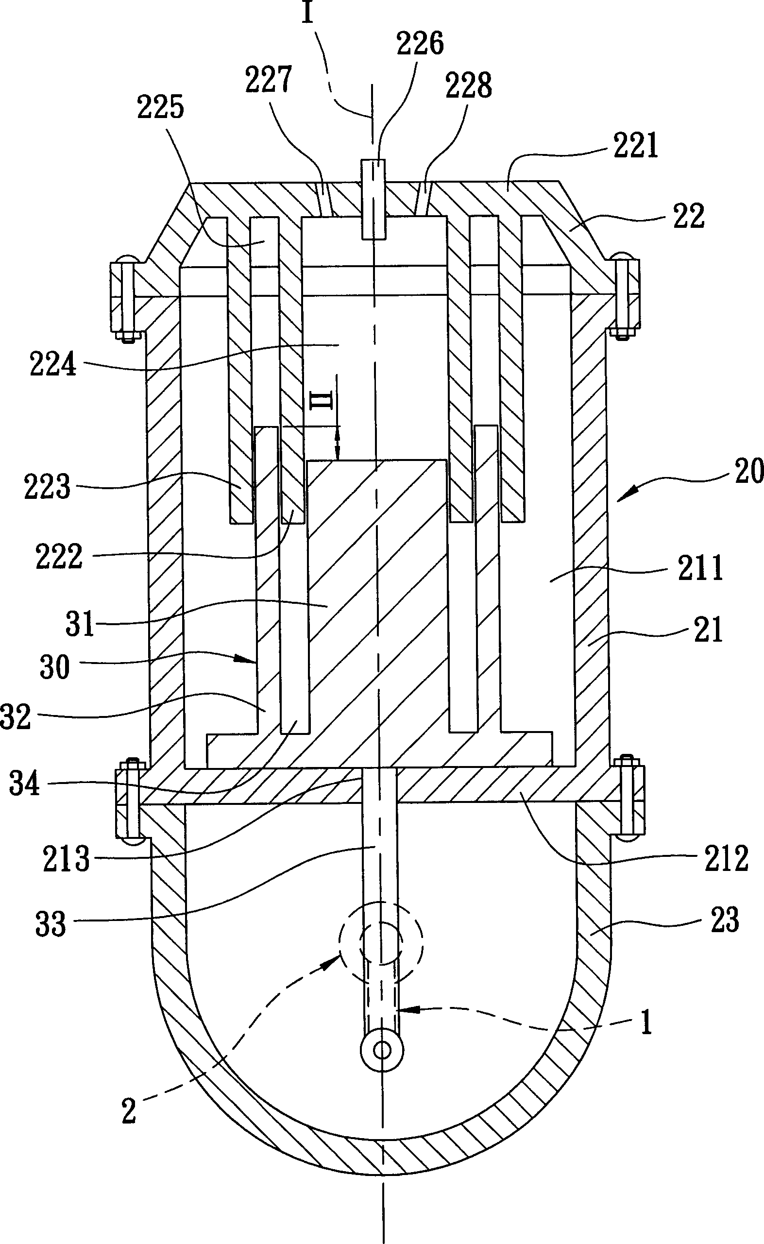
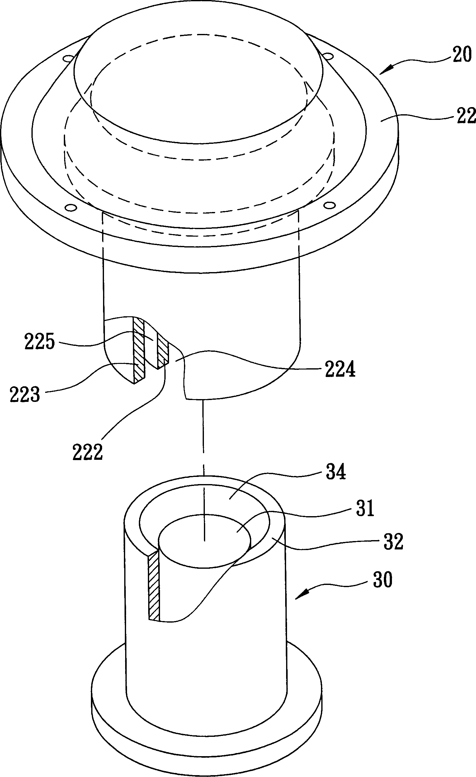
[0021] see figure 2 , image 3 As shown, in the first preferred embodiment of the frictionless power generating device of the present invention, it mainly includes a body unit 20, a piston unit 30, a crank unit 1 and a main shaft 2, and then, the above-mentioned each unit The shape and combined space type are described in detail later.

[0022] The body unit 20 mainly has a cylinder body 21, an upper cover body 22 bolted and fixed above the cylinder body 21, and a shaft seat body 23 bolted and fixed below the cylinder body 21, the cylinder body 21 is hollow inside A chamber 211 is formed, the bottom of which has a closed bottom plate 212, the bottom plate 212 is provided with a sliding hole 213 in the center, the upper cover body 22 is formed with a...


PUM


Abstract

This is a kind of non-friction type air compressing, power generating device. It mainly includes a body element and a piston element. There is a partition wall in the body element. The partition wall encloses a piston air chamber. There are a central ring cover and a sidewall in the piston element. The central ring cover can enter into the piston air chamber. The sidewall is at the outer side of central ring cover. Air in the air chamber is compressed by partition wall to obstruct the air in the air chamber not to leak. Thus, it makes piston element can run up under null friction mode. It also does not generate high temperature.

Description

【Technical field】 [0001] The present invention relates to an air pressure or power generation device, in particular to a frictionless air pressure and power generation device which enables a piston unit to run at high speed in a frictionless contact manner. 【Background technique】 [0002] see figure 1 As shown, a general internal combustion type power machine 10 (such as an engine) mainly includes a cylinder block 11, a set of piston elements 12 that can move up and down in the cylinder block 11, and a crank whose upper end is pivotally connected to the piston element 12. Element 13, and a main shaft 14 that can be driven by the crank element 13, the inner cavity of the cylinder body 11 forms a piston air chamber 111, just for the piston element 12 to slide into the sleeve, the cylinder body 11 is located at the place above the piston air chamber 111 A spark plug 112, an intake valve 113 and an exhaust valve 114 are arranged respectively, so that the fuel enters the piston ...

Claims


Application Information

Patent Timeline
IPC IPC(8): F01B9/02F04B27/12F02B75/32
Inventor 林耀章
Owner 林耀章
Learn More