Blade spring arrangement of rotary compressor

A rotary compressor, leaf spring technology, applied in rotary piston machinery, rotary piston pumps, rotary piston/swing piston pump components, etc., can solve the problem of compressed gas leakage, inconvenience, general products without structure, etc. problem, to achieve the effect of preventing the reduction of work reliability and reducing burrs

Inactive Publication Date: 2007-01-17
LG ELECTRONICS (TIANJIN) APPLIANCES CO LTD
View PDF0 Cites 4 Cited by
  • Summary
  • Abstract
  • Description
  • Claims
  • Application Information

AI Technical Summary

Problems solved by technology

[0015] However, the conventional rotary compressor has a problem that, when machining the vane spring 23, processing the spring housing portion 24 and the lubricating oil supply hole 26 so that the vane housing portion 21 can communicate with the The vane receiving part 21 is connected and intersected with each boundary surface of the spring receiving part 24 and the lubricating oil supply hole 26 to produce burrs. Due to the existence of these burrs, the vane 20 is squeezed out, and the compressed gas is leaked, etc., which reduces the compression. machine reliability issues
[0016] This shows that the above-mentioned existing rotary compressor obviously still has inconvenience and defects in structure and use, and needs to be further improved urgently.
In order to solve the problems existing in the existing rotary compressors, the relevant manufacturers have tried their best to find a solution, but for a long time no suitable design has been developed and completed, and there is no suitable structure for general products to solve the problem. The above-mentioned problems are obviously the problems that relevant industry players are eager to solve

Method used


Image

  • Blade spring arrangement of rotary compressor
  • Blade spring arrangement of rotary compressor
  • Blade spring arrangement of rotary compressor

Examples


Embodiment Construction

[0050] In order to further explain the technical means and effects of the present invention to achieve the intended purpose of the invention, the specific implementation methods, Structure, characteristic and effect thereof are as follows in detail.

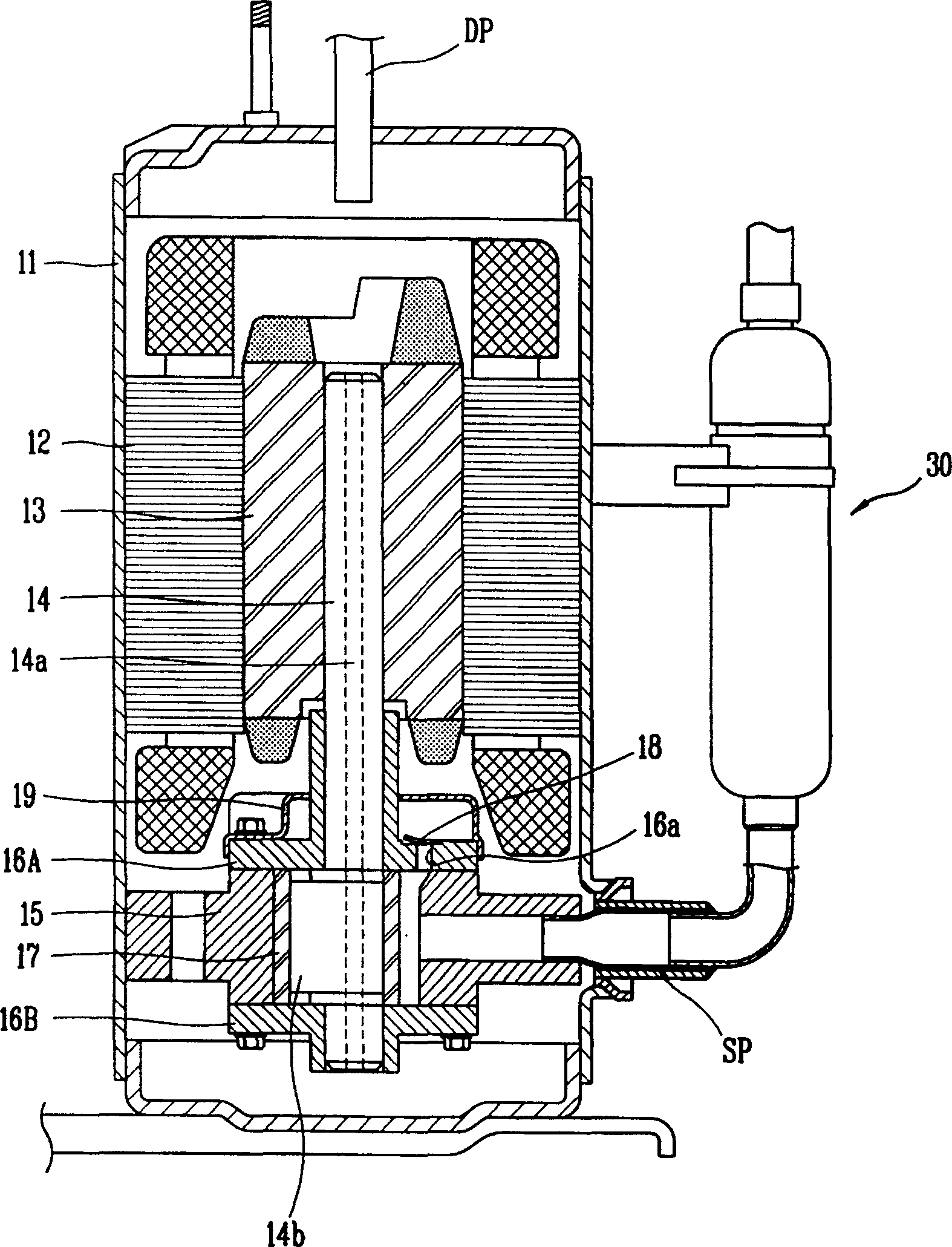
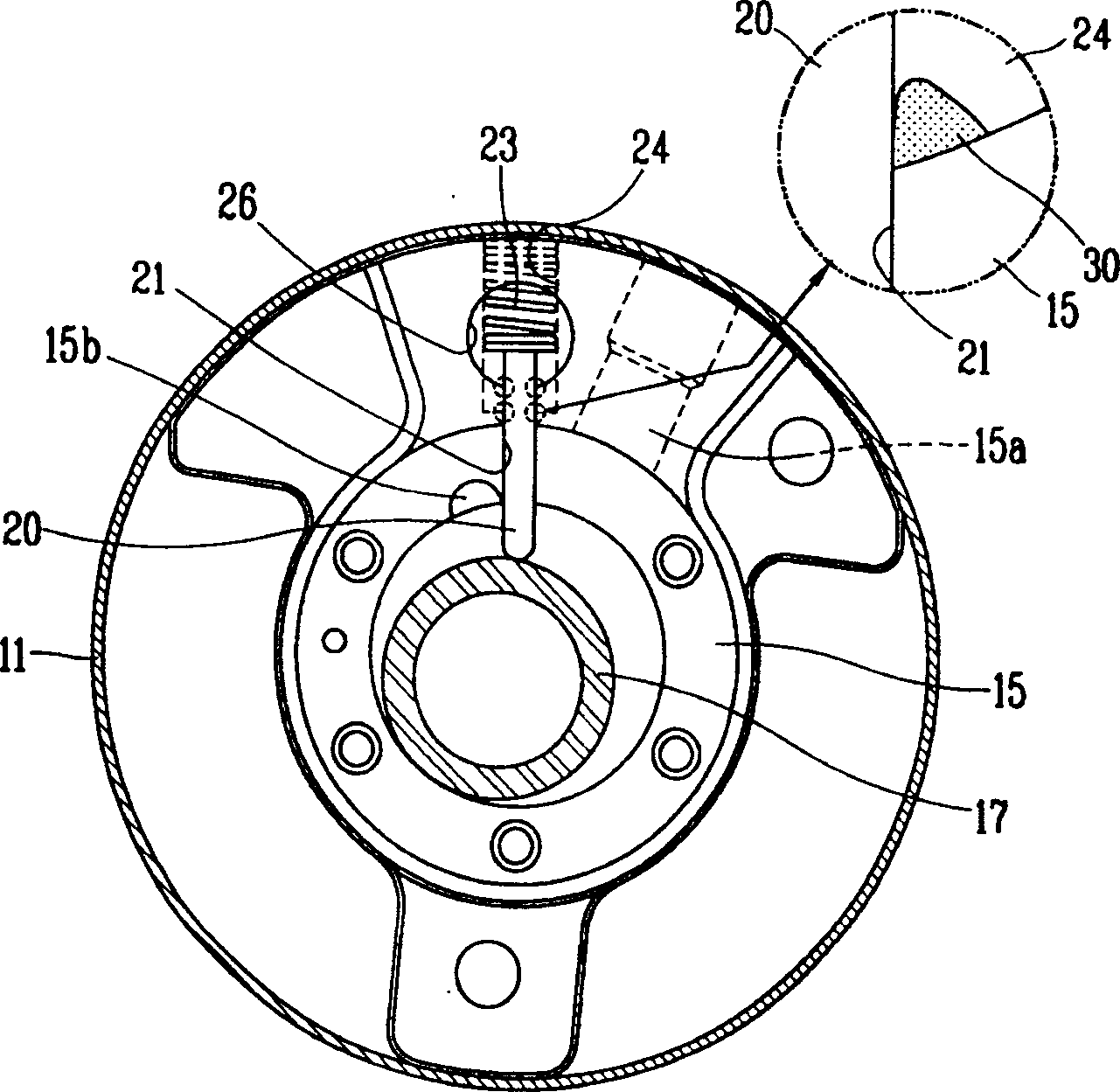
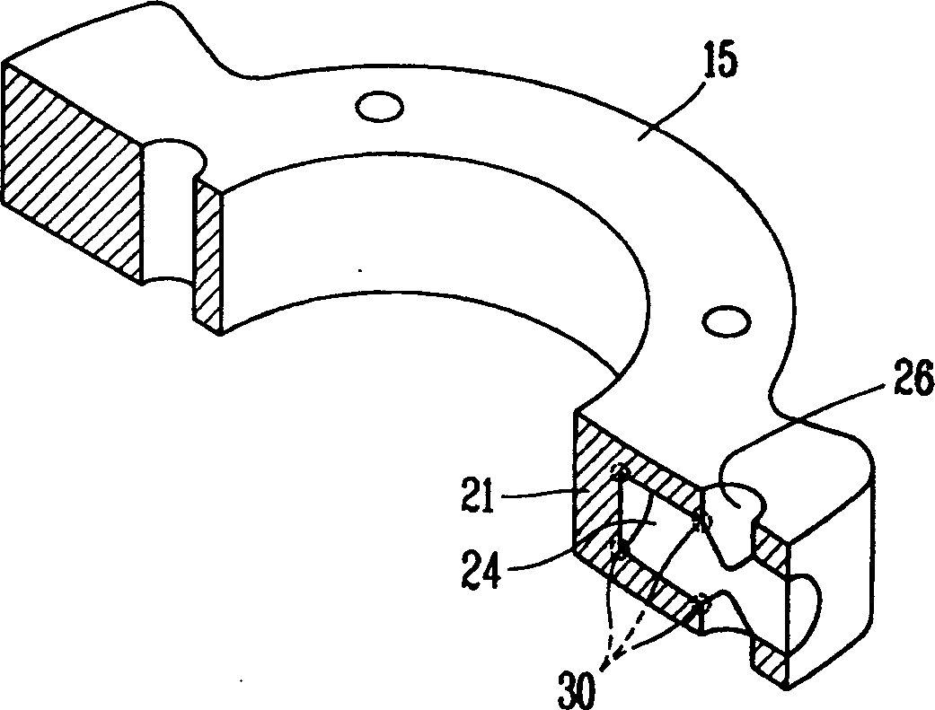
[0051] see Figure 4 to Figure 6 as shown, Figure 4 It is a schematic diagram of a rotary compressor using the vane spring mounting structure according to the present invention, showing the structure of the compression mechanism. Figure 5 , Figure 6 It is a schematic plan view of the structure and working state of the leaf spring according to the present invention.

[0052] It should be noted that, in order to highlight the key points when describing the present invention, well-known functions or configurations will not be described in detail and will be omitted.

[0053] see Figure 4 to Figure 6 As shown, the rotary compressor adopting the leaf spring arrangement structure according to the present invention includes: a ...


PUM


Abstract

This invention is blade spring setting structure of rotating type compressor. It can reduce the formation of trimmings along the blades moving track when assembling the blade spring. It can also prevent reliability from decreasing. The rotating type compressor includes air cylinder setting inside of outer casing; the first and second bearings attaching to both side faces of air cylinder. They cut through the rotating shaft, which is connected to driving electric engine; rotating piston inside of air cylinder. It connects to rotating shaft eccentric part and moves the refrigerant gas at the same time of eccentrically rotating; blades setting through the blade housing part. They carry out straight-line motion along radial direction in pace with the eccentric rotation of rotating piston. The blades also separate the interior of air cylinder into absorbing space and compressing space; blade spring setting inside of the lubricating oil-supplying hole, which communicates to blade housing part along the axial direction of rotating shaft. The blade spring can provide elasticity which makes blades contact with the rotating piston.

Description

technical field [0001] The present invention relates to an arrangement structure of blade springs of rotary compressors in the field of compressors, in particular to a method for installing blade springs, which can reduce the burr generated on the motion track of the blades, and can also The installation structure of the vane spring of the rotary compressor (STRUCTURE FOR INSTALLING VANE SPRING OF ROTARY COMPRESSOR) that prevents the subsequent decrease in reliability. Background technique [0002] In general, a rotary compressor used in an air conditioner etc. has a structure in which a rotary piston of the compression mechanism part is eccentrically coupled to a rotary shaft integrally formed with the motor mechanism part, and the rotary piston sucks in while rotating in a circular cylinder. The gaseous refrigerant is compressed and then discharged. [0003] see figure 1 , figure 2 and image 3 as shown, figure 1 is a schematic longitudinal sectional view of a rotary...

Claims


Application Information

Patent Timeline
Patent Type & Authority Applications(China)
IPC IPC(8): F04C29/00F04C18/356
Inventor 赵承衍
Owner LG ELECTRONICS (TIANJIN) APPLIANCES CO LTD
Why Eureka
Try Eureka