Differential piesoelectric two dimension acceleration sensor

An acceleration sensor and differential technology, applied in the field of two-dimensional piezoelectric acceleration sensors, can solve the problems of low sensitivity, weak output signal, and inability to overcome measurement errors, and achieve high sensitivity, strong output signal, and light weight Effect

Inactive Publication Date: 2007-01-24
CHONGQING UNIV
View PDF0 Cites 9 Cited by
  • Summary
  • Abstract
  • Description
  • Claims
  • Application Information

AI Technical Summary

Problems solved by technology

The other is the shear and compression composite two-dimensional piezoelectric acceleration sensor, that is, it is installed on the base after combining two sets of piezoelectric elements in such a way that the maximum sensitivity axis is 90° to each other, and then the piezoelectric element After preloading the inertial mass on the upper body, weld the shell and the base together (see figure 2 ), however, this two-dimensional piezoelectric acceleration sensor has a weak output signal when the external force is small, and the sensitivity is not high, and it cannot overcome the measurement error caused by the change of the environment

Method used


Image

  • Differential piesoelectric two dimension acceleration sensor
  • Differential piesoelectric two dimension acceleration sensor
  • Differential piesoelectric two dimension acceleration sensor

Examples


Embodiment 1

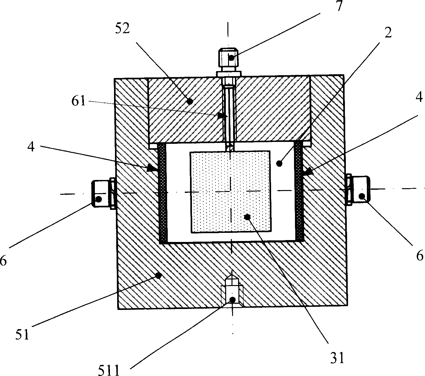
[0022] Embodiment 1 (with reference to image 3 , 4 , 9, 10):

[0023] This example is an example of improving the reliability of the invention on the basis of the general introduction. Both sides of the four quartz wafers (31, 32, 33, 34) in this example have a relatively long and a relatively short electrode (82, 81) all located in the middle of their upper parts. On the top of the inertial mass 1, there is a cross-shaped wiring groove 11 whose opening corresponds to the electrodes (82, 81) of each quartz wafer (31, 32, 33, 34), and one end is connected to the signal of each electrode (82, 81). After the lead wires 61 gather at the intersection of the cross-shaped wiring groove 11 , they are connected with the connecting plug 7 .

Embodiment 2

[0024] Embodiment 2 (with reference to image 3 , 4 , 5, 6, 7, 8):

[0025] This example is a good example to further improve the reliability of the invention and ensure the manufacturability on the basis of the general description part or embodiment 1. In this example, the four quartz wafers (31, 32, 33, 34) are all squares whose four sides are parallel to the corresponding surface of the inertial mass 1 but smaller than the corresponding surface. Wherein the power transmission block 4 is equal to the height of the wafer positioning frame 2, equal to the nominal size of the width of the quartz wafer (31, 32, 33, 34) and completely overlapped, but the upper deviation of its width value is not greater than that of the quartz wafer (31, 34). 32,33,34) of the lower deviation---like this, it has been further ensured that the force transmission block 4 can reliably transmit the sensed acceleration signal to the quartz wafer (31,32,33,34).

Embodiment 3

[0026] Embodiment 3 (with reference to image 3 , 4 ):

[0027] This example is an example of further improving the reliability of the invention on the basis of the general introduction, embodiment 1 or embodiment 2. In the base of this example, there is a spacer chamber whose depth is 1-2mm smaller than the height of the wafer spacer 2, and the other corresponding dimensions are equal to the wafer spacer 2, and each of the four walls of the chamber has a depth The positioning groove of the force transmission block 4 that is 0.5 to 1 mm thicker than the force transmission block 4 and whose width is equal to the force transmission block 4 . The case cover 52 of the base is fixed on the case body 51 of its base (that is to say, this case cover 52 is fixedly covered on the base with its bottom surface and the contact state of the wafer positioner 2 top surface being the pure position-limiting contact state. When on the box body 51 of seat, promptly will guarantee the position-...


PUM


Abstract

The sensor includes following parts and structures: insulative inertial mass block in cube; four pieces of XO0 cutting type quartz wafer with electrode are jointed four walls of the inertial mass block; the inertial mass block and quartz wafers are instilled inside base frame composed of case body and case cover. Each insulative force transmission block is pasted on outside each quartz wafer. Pretension screw of withstanding each piece of force transmission block is arranged on four walls of the base frame. Through signal lead wire, one end of the case cover is connected to electrode, and the other end is connected to connector plug, which is connected to differential type charge amplifier. The sensor possesses high sensitivity, or, when outside force is smaller, output signal is still strong so as to reduce measuring error brought from environmental change. Features of the sensor are: light weight, simple structure, easy of manufacture.

Description

technical field [0001] The invention relates to an acceleration sensor, in particular to a two-dimensional piezoelectric acceleration sensor. Background technique [0002] Two-dimensional acceleration sensors can simultaneously measure vibration or shock acceleration in two directions in space. At present, the known two-dimensional piezoelectric acceleration sensor mainly adopts two schemes, one is composed of two unidirectional acceleration sensors with independent outputs installed in a metal shell perpendicular to each other, that is, this two-dimensional acceleration sensor consists of a single Acceleration sensor and connection block (see figure 1 ), obviously, the size and weight of this type of sensor are too large. The other is the shear and compression composite two-dimensional piezoelectric acceleration sensor, that is, it is installed on the base after combining two sets of piezoelectric elements in such a way that the maximum sensitivity axis is 90° to each oth...

Claims


Application Information

Patent Timeline
Patent Type & Authority Applications(China)
IPC IPC(8): G01P15/09G01P15/18
Inventor 秦岚刘俊刘京诚李敏
Owner CHONGQING UNIV
Why Eureka
Try Eureka