Piezoelectric loudspeaker

A loudspeaker, piezoelectric technology, applied in the field of loudspeakers, can solve problems such as too large

Inactive Publication Date: 2007-01-31
IND TECH RES INST +1
View PDF1 Cites 8 Cited by
  • Summary
  • Abstract
  • Description
  • Claims
  • Application Information

AI Technical Summary

Problems solved by technology

Moreover, the volume of this design device is about 94 × 72 × 20 millimeters (mm), which is too large

Method used


Image

  • Piezoelectric loudspeaker
  • Piezoelectric loudspeaker
  • Piezoelectric loudspeaker

Examples


Embodiment Construction

[0025] In order to have a further understanding of the purpose, structure, features and functions of the present invention, now cooperate with accompanying drawing to describe in detail as follows:

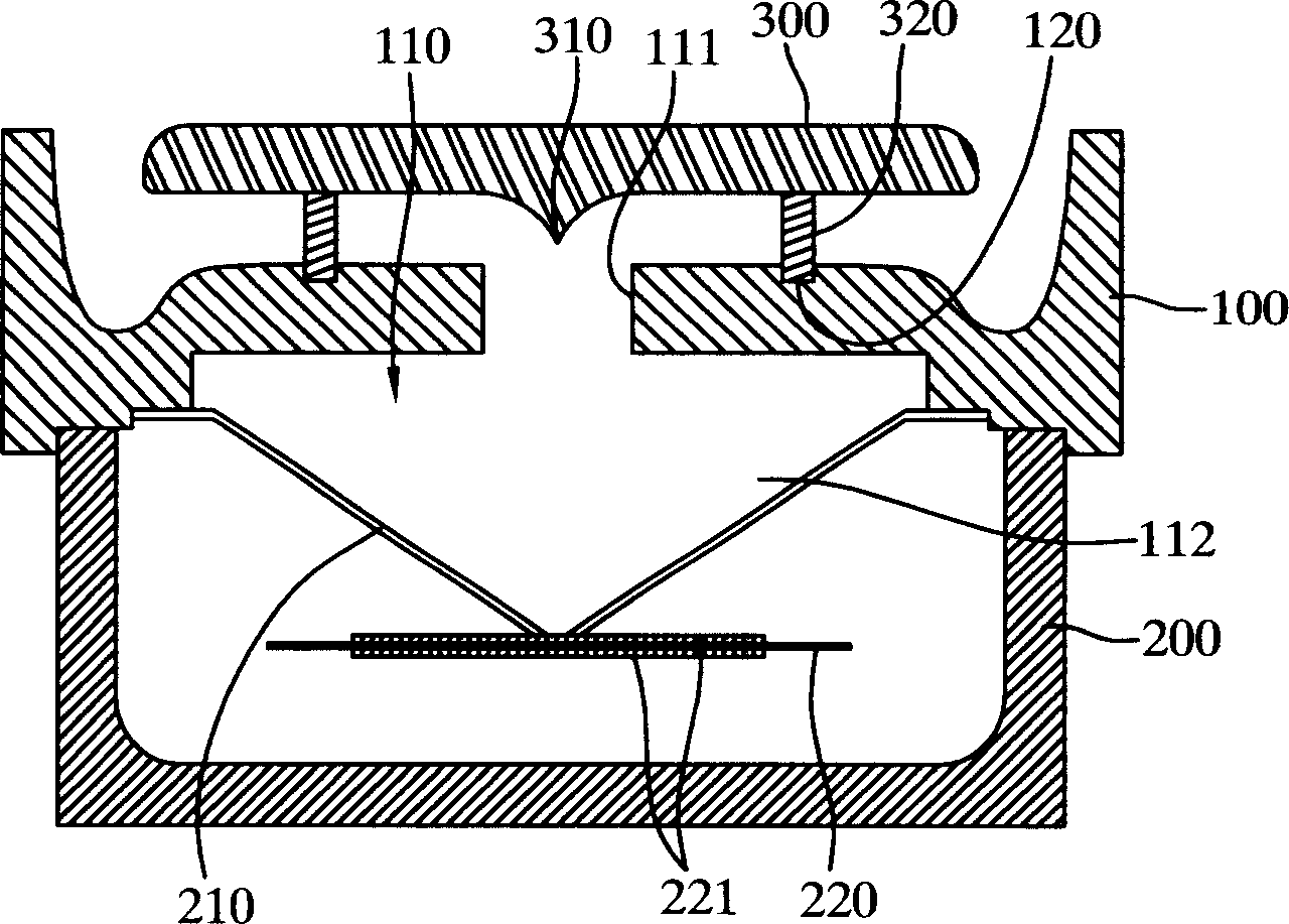
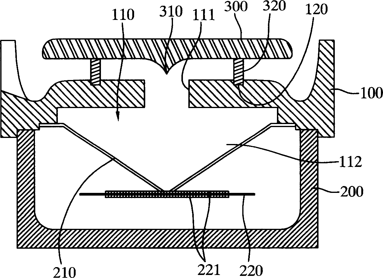
[0026] figure 1 It is a schematic cross-sectional view of the first preferred embodiment of the present invention. The loudspeaker is an axisymmetric device, including a frame body 100 with a cylindrical opening 111 , a front cover 300 , a rear cover 200 , a diaphragm 210 and a piezoelectric actuator. The upper surface of the frame body has three joint holes 120 and a curved surface; the front cover is fixed on the top of the frame body 100 with a short column as a joint component, and the lower edge of the frame body 100 is bonded with the rear cover 200 to form a cavity , the diaphragm 210 and the piezoelectric actuator are arranged in the cavity, and the hanging edge of the diaphragm 210 is connected with the frame body 100 to form an air chamber 112, and the air chamber 112 a...


PUM


Abstract

This invention relates to a piezoelectric loudspeaker to generate sound wave transmitting to the external space, and improve sound pressure standard and useable frequency range through combining sound wave channels which have resonant cavity with space resonant frequency and increased cross-sectional area. The sound wave channel has an inlet and an outlet, in which, the inlet links the opening of the resonant cavity. The outlet leads to the external space which cross-sectional area increases from the inlet to the outlet. The sound wave from resonant cavity enters into the sound wave channel through the opening and the external space followed. The resonant cavity connects and compresses air to generate sound wave by dint of mechanical deformation from piezoelectric actuator. The wave is amplified by resonance in the cavity, and then transmits to the channel external space through wave channel.

Description

technical field [0001] The invention relates to a loudspeaker, in particular to a piezoelectric loudspeaker. Background technique [0002] Piezoelectric speakers (piezoelectric loudspeakers) are speakers that use piezoelectric elements (piezoelectric elements) as a driving thrust source for sound waves, and can be used to generate sound waves in a frequency range that can be received by ordinary human ears. Generally, the piezoelectric component can be a piezoelectric ceramic sheet. When the input voltage signal enters the upper and lower surfaces of the piezoelectric component from small to large, due to the piezoelectric effect, the piezoelectric component will produce radial mechanical deformation, and then Bending deformation in the up and down direction causes the shape of the piezoelectric component to change from a flat surface to a convex surface; when the input voltage signal is reversed, the shape of the piezoelectric component turns into a concave surface, and in ...

Claims


Application Information

Patent Timeline
Patent Type & Authority Applications(China)
IPC IPC(8): H04R17/10
CPCB06B1/0603G10K9/122H04R1/025H04R27/04
Inventor 颜坤龙杨智铭
Owner IND TECH RES INST
Why Eureka
Try Eureka