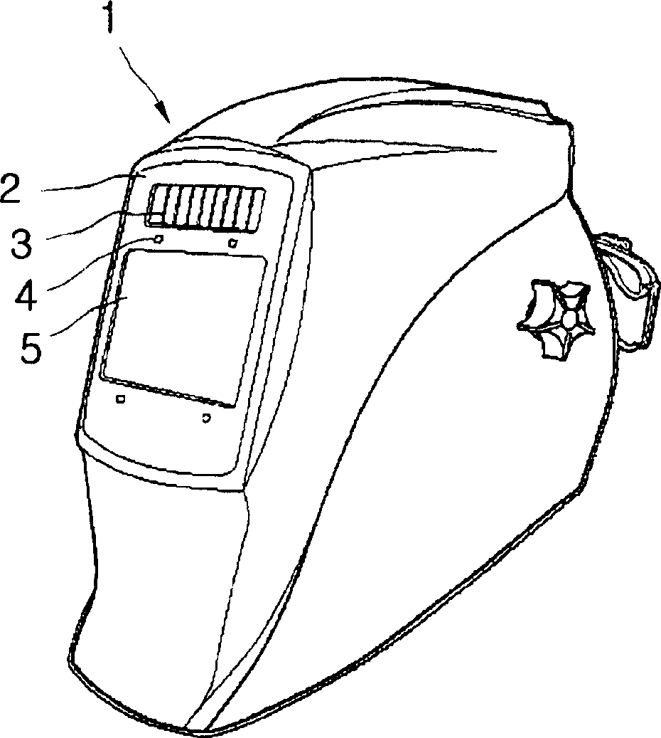
Dazzle prevention device having electromagnetic wave detection function
An electromagnetic wave and functional technology, applied in the field of anti-glare devices, can solve problems such as wrong operation, disturbing the operator's precise operation, hindering the operator from performing work, etc., and achieve the effect of preventing wrong operation
- Summary
- Abstract
- Description
- Claims
- Application Information
AI Technical Summary
Problems solved by technology
Method used
Image

Examples
Embodiment Construction
[0043] The invention will now be described in detail with reference to preferred embodiments thereof with reference to the accompanying drawings, wherein like reference numerals designate like or similar elements throughout the different views.
[0044] The constitution and operation of the present invention are described in detail with reference to the accompanying drawings.
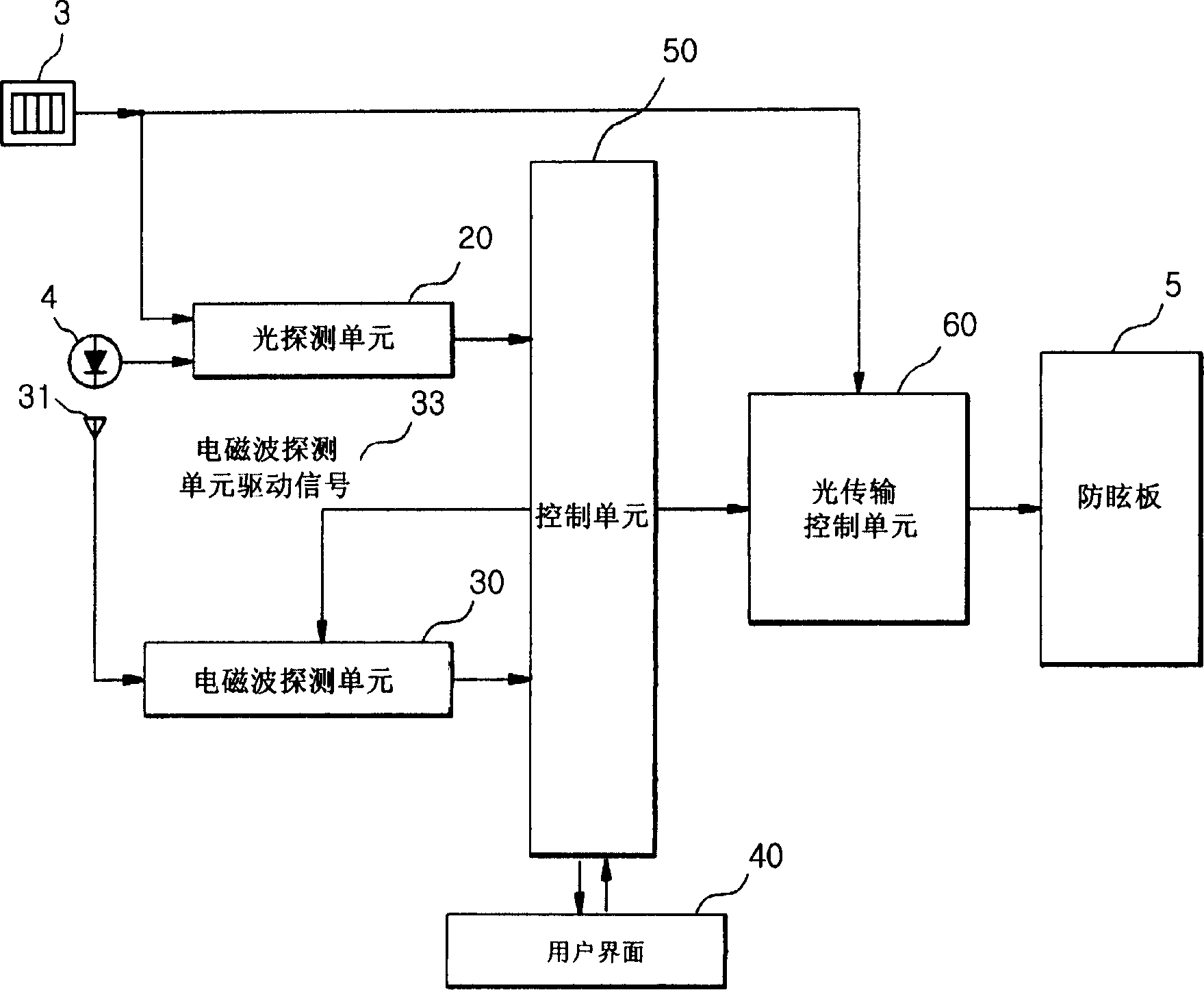
[0045] image 3 is a structural diagram showing the electromagnetic wave detection and anti-glare device according to the present invention. Figure 4 is a circuit diagram showing the electromagnetic wave detection unit 30 of the anti-glare device having an electromagnetic wave detection function according to the present invention.
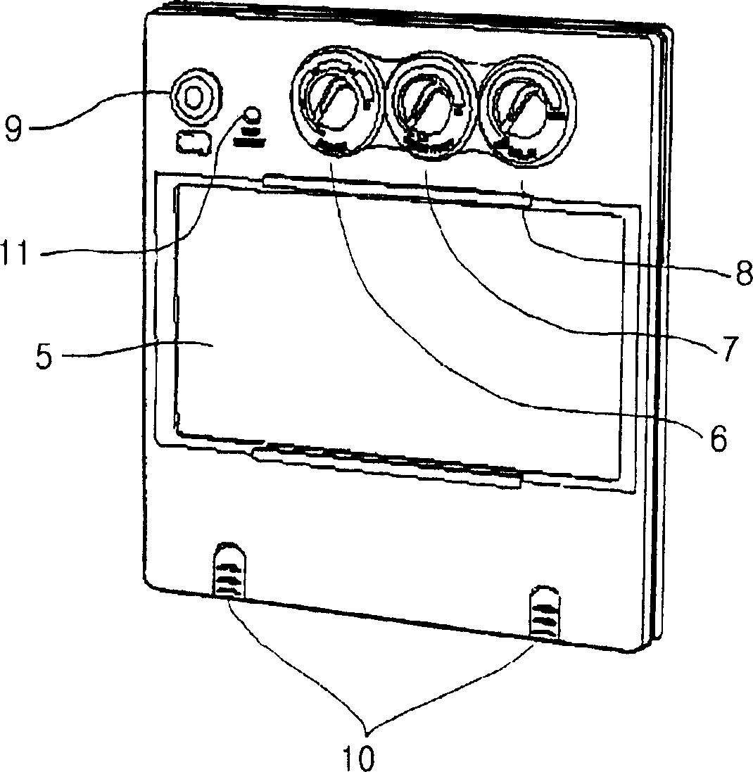
[0046] Such as image 3 Said, the anti-glare device with electromagnetic wave detection function according to the present invention includes a light detection unit 20 , an electromagnetic wave detection unit 30 , a user interface 40 , a control unit 50 and a light transmi...
PUM
 Abstract
Description
Claims
Application Information
 - R&D
- Intellectual Property
- Life Sciences
- Materials
- Tech Scout
- Unparalleled Data Quality
- Higher Quality Content
- 60% Fewer Hallucinations
Browse by: Latest US Patents, China's latest patents, Technical Efficacy Thesaurus, Application Domain, Technology Topic, Popular Technical Reports.
© 2025 PatSnap. All rights reserved.Legal|Privacy policy|Modern Slavery Act Transparency Statement|Sitemap|About US| Contact US: help@patsnap.com