Insulation package arrangement for insulating the interior of an aircraft fuselage

A technology for aircraft fuselage and packaging devices, which is applied in the field of fire-proof or fire-proof devices and isolation packaging devices, which can solve the problems of prolonging the fire-resistant time and melting of attachments, and achieve the effect of convenient evacuation and prolonged time

Inactive Publication Date: 2007-01-31
AIRBUS OPERATIONS GMBH
View PDF2 Cites 12 Cited by
  • Summary
  • Abstract
  • Description
  • Claims
  • Application Information

AI Technical Summary

Problems solved by technology

[0007] Furthermore, traditional isolation attachments are made of non-metallic materials (plastics), which may melt in a fire
Thus, it is always desirable to prolong the fire resistance time of the attachment and keep the insulation in place to prevent the (burning) insulation (insulation package) from falling - such a fall would cause uncontrolled damage inside the aircraft. obstacle

Method used


Image

  • Insulation package arrangement for insulating the interior of an aircraft fuselage
  • Insulation package arrangement for insulating the interior of an aircraft fuselage
  • Insulation package arrangement for insulating the interior of an aircraft fuselage

Examples


Embodiment Construction

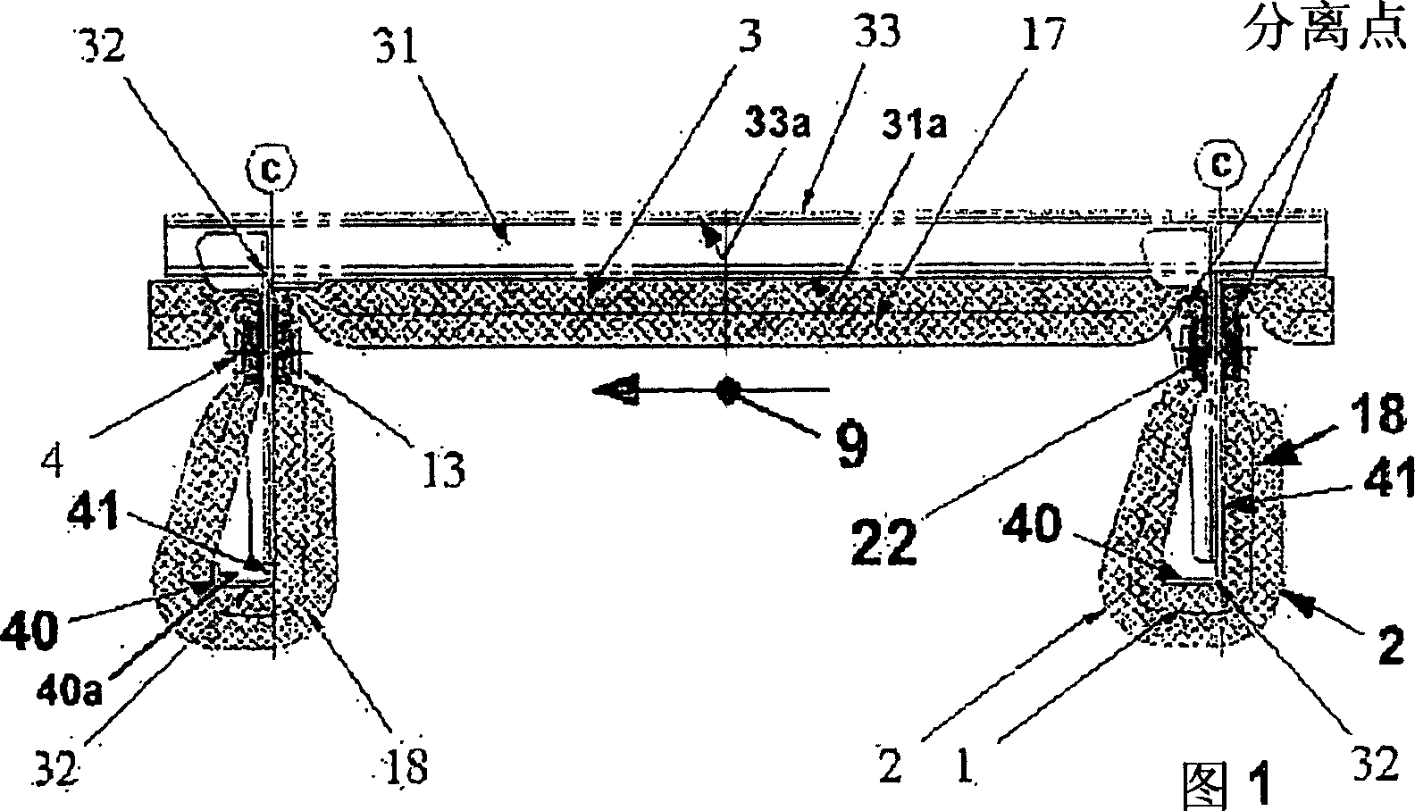
[0026] For an easier understanding of FIG. 1 , which shows a separator, it should be mentioned as an introduction that the structural element of the aircraft fuselage not only includes stringers 31 , but also ribs 32 , wherein with the aid of stringers The strips reinforce all the panels of the outer skin 33 of the aircraft fuselage structure, while the ribs are arranged (approximately) at a distance c perpendicular to the longitudinal axis 9 of the aircraft and are attached to the stringers 31 . A (so-called) rib support 40 is bonded to these ribs 32 at the non-attached end, the rib support 40 extending parallel to the longitudinal axis 9 of the aircraft, wherein the rib support (according to the present embodiment) 40 (unattached free) end is angled perpendicular to the longitudinal axis 9 of the aircraft.

[0027] FIG. 1 shows the insulation package 3 (of the fuselage insulation) in a position (near) on the outer skin 33 of the aircraft (with general reference characteristi...


PUM


Abstract

according to an exemplary embodiment, which may be installed near the fuselage structure, is believed protect the cabin region of an aircraft against fire whose flames act on the insulation package from outside the aircraft environment, thus clearly facilitating evacuation of the passangers from the vehicle. The insulation package arrangement may comprise several fuselage insulation packages (19-22) of an elongated form. These packages may adjoin the aircraft fuselage structure in the direction of the longitudinal axis (9) of the aircraft. They may longitudinally adjoin a support surface (31a) of the stringers (31) which are attached to the aircraft fuselage, or longitudinally adjoin an inner area (33a) of a panel of outer skin and are attached to both longitudinal sides of the ribs (32). Furthermore those insulation packages (19-22) may be completely enclosed by a burn-through-proof foil (11) which is arranged in a space enclosed by interior paneling and by the panels of the outer skin. The design of a fuselage insulation package may be implemented with burn-throughproof insulation of a larger cross section and / or a burn-through-proof barrier layer of a smaller cross section which are arranged within the fuselage insulation package either singly or in combination. In this arrangement, the insulation or the barrier layer extends near to or adjacent to an interior wall region of the foil wall. As an alternative only that insulation which on the longitudinal end of the fuselage insulation package continues outward with a flat insulation end section is atteched outside of and adjacent to the foil (11) circumference of the fuselage insulation package (19-22). Said end section of insulation is attached to a rib-attachment region which is arranged below the respective longitudinal sides of a rib (32) and near the stringer (31) by means of burn-through-proof attachment elements (4, 13).

Description

[0001] Cross References to Related Applications [0002] This application claims priority from DE 10 2004 001 049, filed 5 January 2004, and US 60 / 600,106, filed 9 August 2004, both of which are incorporated herein by reference. technical field [0003] The invention relates to an insulation, such as a fire or fire protection, for an aircraft. In particular, the present invention relates to insulation encapsulation for isolating the interior of an aircraft fuselage. Background technique [0004] A conventional isolation system is known, as shown in Fig. 1 , which generally comprises a core material and an isolation material embedded in an isolation package, and also includes an envelope. The core material and insulating material may comprise products of the fiber industry, in particular for which glass fiber material (glass wool) is widely used. This material satisfies the considered thermal and acoustic insulation requirements quite well. In order to install (attach) the...

Claims


Application Information

Patent Timeline
Patent Type & Authority Applications(China)
IPC IPC(8): B64C1/40B64D25/00
CPCB64D25/00B64C1/40
Inventor 雷纳·穆勒彼得·图兰斯基维尔科·厄斯特赖希托尔斯滕·赖内尔特
Owner AIRBUS OPERATIONS GMBH
Why Eureka
Try Eureka