Cooling device for working machine

A technology for cooling devices and operating machinery, applied in engine cooling, mechanical equipment, air cooling, etc., can solve problems such as inability to clean, increased pressure loss on the suction side, and inability to swing out the heat exchanger 11, etc., to achieve easy cleaning , Simple installation structure and easy maintenance

Inactive Publication Date: 2007-01-31
SHIN CATERPILLAR MITSUBISHI LTD CORP
View PDF1 Cites 3 Cited by
  • Summary
  • Abstract
  • Description
  • Claims
  • Application Information

AI Technical Summary

Problems solved by technology

[0013] That is, the most suitable installation angles of the sound-insulating rectifying panels 17 corresponding to the body shape and performance of each model are various, and even for the same body, the intake air volume and suction angle will vary according to different operating conditions. different, therefore, the fixed sound insulation rectifying plate 17 in the past can not deal with
[0014] Moreover, if the installation angle of the fixed sound-insulating rectifying plate 17 is inappropriate, the sound-insulating rectifying plate 17 will hinder the intake of cooling air, the pressure loss on the suction side will increase, and the suction efficiency will deteriorate.
On the other hand, there is also the problem of long analysis time when calculating the possible installation angle of the sound insulation rectifying plate 17
[0015] In addition, in the conventional fixed sound insulation rectification plate 17, when cleaning the heat exchanger 11 of the cooling unit from the side door side during maintenance, if the sound insulation rectification plate 17 is located on the near side, it will be difficult to clean or cannot be cleaned. problem of where to go
[0016] Similarly, when cleaning the heat exchanger 11, it is necessary to take off the filter screen positioned at the front side of the heat exchanger 11. Since the filter screen must be disassembled, it must be carried out in the gap between the sound insulation rectifying plate 17 and the heat exchanger 11, so it is more difficult , may damage the heat exchanger 11
In addition, since the gap between the sound-insulating rectifying plate 17 and the heat exchanger 11 is small, it is difficult to insert the nozzle used for cleaning, and the heat exchanger 11 may also be damaged.
[0017] In addition, in order to improve the cleaning efficiency of the heat exchanger 11 of the cooling assembly, the heat exchanger 11 is made into a structure that can be swung out (swing out), but because of the sound insulation rectifying plate 17, the heat exchanger 11 cannot be swung out. , it may not be possible to clean the heat exchanger 11

Method used


Image

  • Cooling device for working machine
  • Cooling device for working machine
  • Cooling device for working machine

Examples


Embodiment Construction

[0072] Below, refer to Figure 1 to Figure 17 The various embodiments shown illustrate the invention. In addition, in the description of the present invention, the hydraulic excavator as the working machine shown in FIG. 18 is also referred to, so the parts corresponding to the parts in FIG. 18 are given the same reference numerals.

[0073] based on Figure 1 to Figure 3 , Embodiment 1 of a cooling device for a hydraulic excavator will be described.

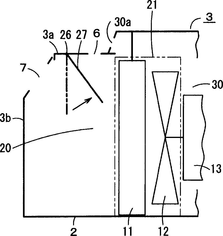
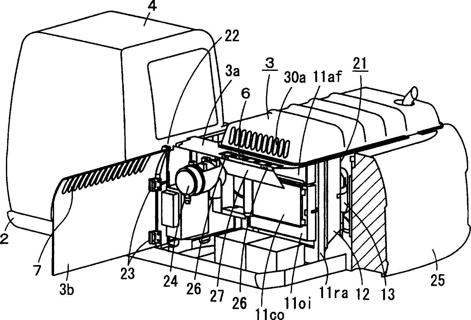
[0074] Such as figure 1 As shown, in the cooling device room 20 of the hydraulic excavator, a cooling assembly 21 is provided. The cooling assembly 21 has a heat exchanger 11 and a cooling fan 12 for cooling a radiator of the engine, and is covered by a cover 3. 21 and engine 13. The cover 3 has an upper cover 3 a provided above the cooling unit 21 , and a side door 3 b serving as a side cover provided on one side of the upper cover 3 a and facing the cooling unit 21 .

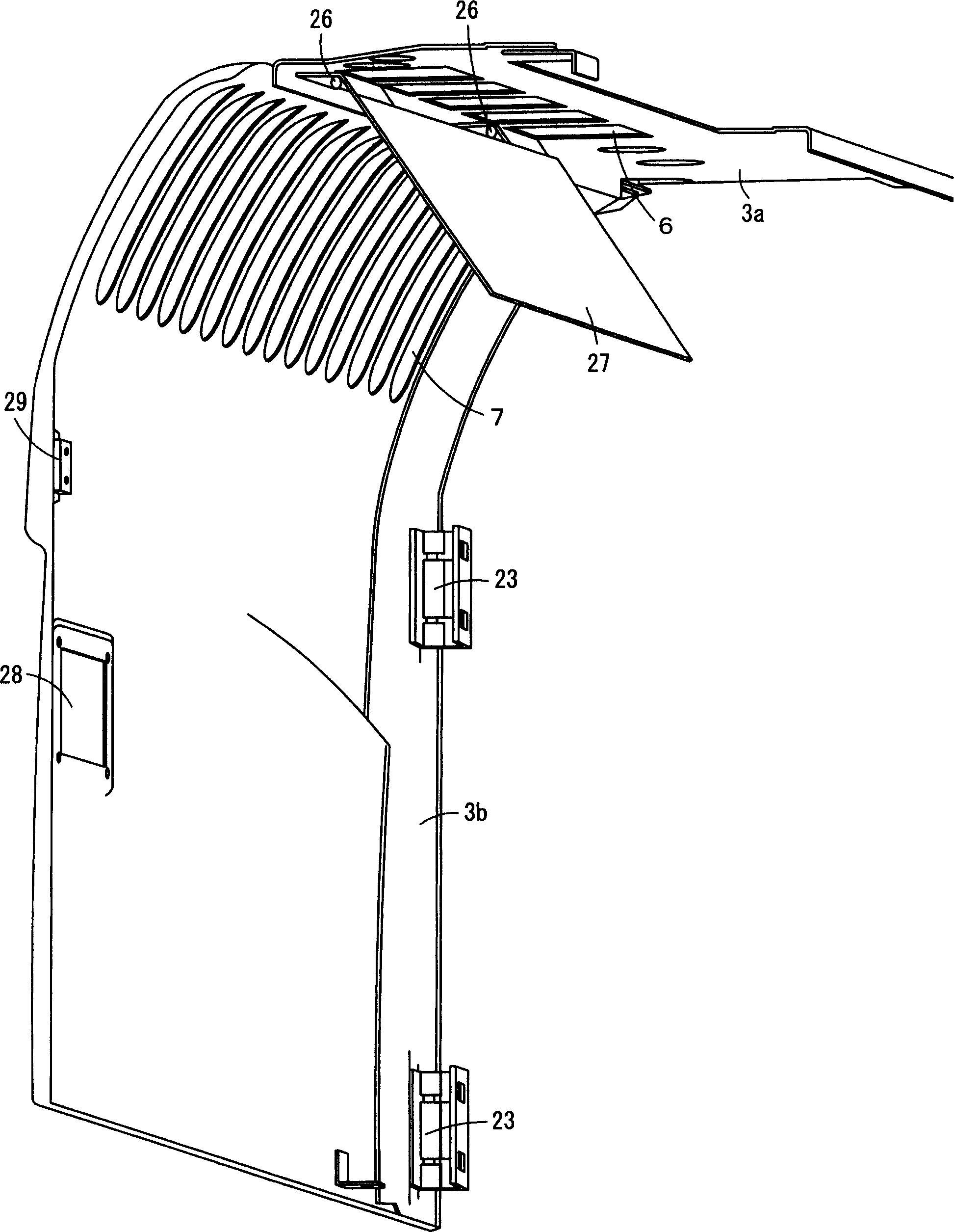
[0075] Such as figure 2 As shown, the side door 3b...


PUM


Abstract

A cooling device for a working machine having a sound- insulating / flow-straightening plate, the cooling device being capable of meeting different working machine models and working conditions. An upper cover (3a) is placed above a cooling package (21) having a heart exchanger (11) and a cooling fan (12), and a side door (3b) is provided at one side of the upper cover (3a) so as to face the cooling package (21). The upper cover (3a) has an upper air inlet hole (6) between the side door (3b) and the cooling package (21), and a side air inlet hole (7) is opened in an upper section neighboring on the upper cover, at a side door (3b). A sound-insulating / flow-straightening plate (27) is pivotally installed by a hinge (26) disposed between the upper air inlet hole (6) and the side air inlet hole (7). The angle of inclination of the sound-insulating / flow-straightening plate (27) is automatically determined by balance between pressures of airflows sucked by the upper air inlet hole (6) and the side air inlet hole (7). The sound-insulating / flow-straightening plate (27) shields internally produced sound and straighten the air sucked from the upper air inlet hole (6) and the side air inlet hole (7).

Description

technical field [0001] The invention relates to a cooling device for a working machine with a cooling unit having at least a heat exchanger for cooling a radiator of an engine and a cooling fan. Background technique [0002] As shown in FIG. 18, as a hydraulic excavator as a working machine, an upper rotating body 2 is rotatably arranged on a lower traveling body 1 through a rotating bearing portion, and a power unit covered with a cover 3 is placed on the upper rotating body 2. A cab 4 and a front working device 5 are also mounted. [0003] In the cover 3, the upper air intake hole 6 is opened on the upper cover 3a fixed to one side, and the side air intake hole 7 is opened on the upper part of the side door 3b, which is installed so as to be freely openable with respect to the upper cover 3a. close. [0004] Such as Figure 19 As shown, in the power room inside the cover 3, the following power plant-related equipment is provided: a cooling assembly integrating a heat exc...

Claims


Application Information

Patent Timeline
Patent Type & Authority Applications(China)
IPC IPC(8): F01P11/10F01P11/12E02F9/00
CPCF01P2025/48E02F9/0891F01P11/12E02F9/0866F01P2001/005F01P11/10E02F9/00
Inventor 山田恭子田中裕也山下康夫
Owner SHIN CATERPILLAR MITSUBISHI LTD CORP
Why Eureka
Try Eureka