Heat exchanger and air conditioner using the same

A heat exchanger and mechanical technology, applied in heat exchange equipment, evaporator/condenser, refrigerator, etc., can solve the problems of increased pressure loss in the heat transfer tube, failure to obtain heat transfer performance, collapse of the peak shape, etc. Achieves the effects of improved recyclability, improved tightness, and easy decomposition

Active Publication Date: 2012-11-14
MITSUBISHI ELECTRIC CORP
View PDF1 Cites 0 Cited by
  • Summary
  • Abstract
  • Description
  • Claims
  • Application Information

AI Technical Summary

Problems solved by technology

However, when the tube is expanded to fix the heat transfer tube to the fins, the peak shape of the inner surface collapses, and the heat transfer performance equal to or higher than that of the copper tube cannot be obtained.
[0005] In addition, since aluminum is weaker than copper, it is necessary to increase the thickness of the groove bottom of the heat transfer tube, which increases the pressure loss inside the heat transfer tube.

Method used


Image

  • Heat exchanger and air conditioner using the same
  • Heat exchanger and air conditioner using the same
  • Heat exchanger and air conditioner using the same

Examples


Embodiment approach 1

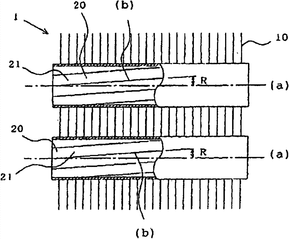
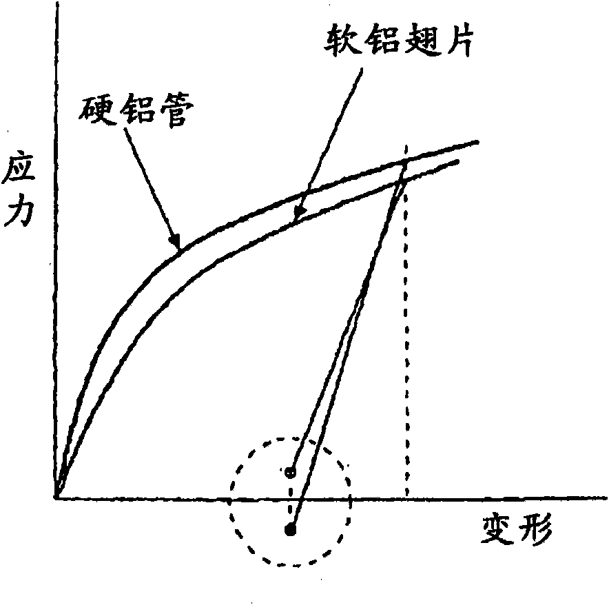
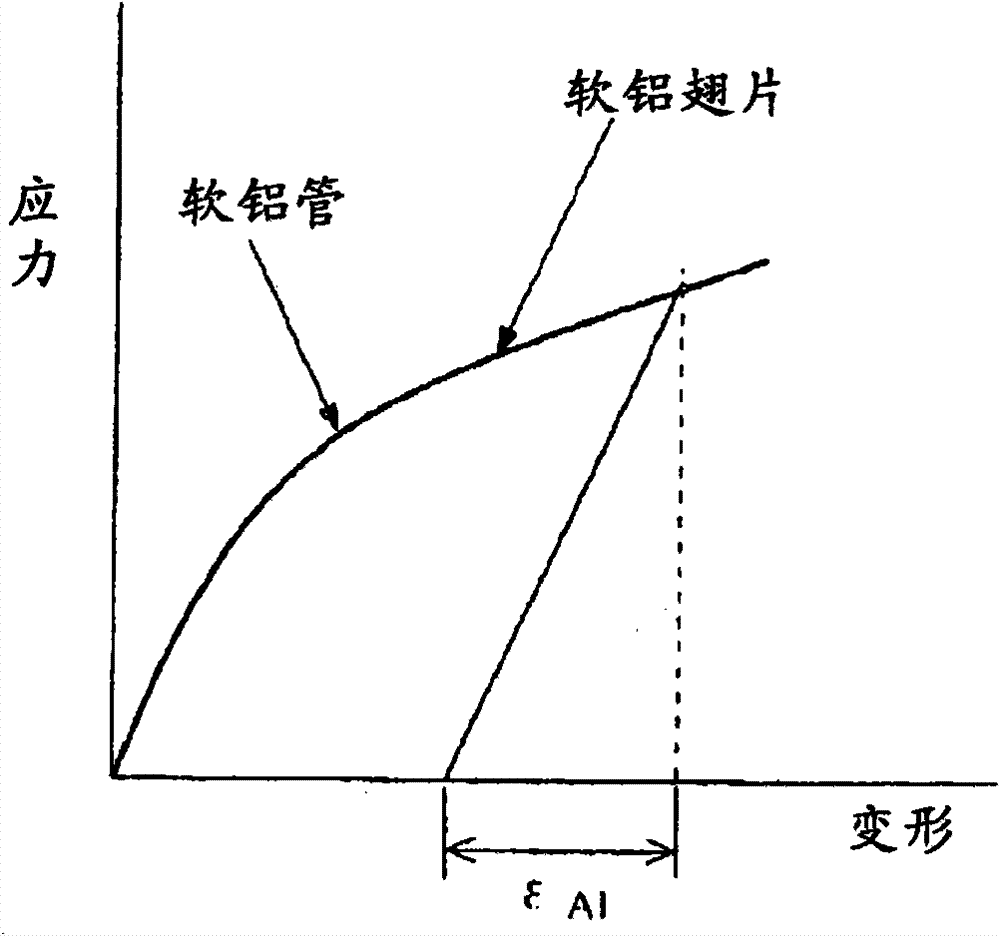
[0028] figure 1 It is a front cross-sectional view of the heat exchanger according to Embodiment 1 of the present invention cut in the vertical direction, figure 2 is a graph showing the relationship between deformation and stress of an aluminum tube with high deformation resistance and an aluminum fin with low deformation resistance, image 3 is a graph showing the relationship between deformation and stress of an aluminum tube with low deformation resistance and an aluminum fin with low deformation resistance, Figure 4 It is a graph showing the relationship between the lead angle and the increase rate of the evaporation pressure loss.

[0029] exist figure 1 Among them, the heat exchanger 1 has fins 10 and heat transfer tubes 20 passing through the fins 10 . The fins 10 are made of a (soft) aluminum-based material with low deformation resistance. In addition, the heat transfer tube 20 is made of (hard) aluminum or an aluminum alloy (hereinafter referred to as aluminum-...

Embodiment approach 2

[0035] Figure 5 It is a side cross-sectional view of the heat exchanger 1 according to Embodiment 2 of the present invention cut in the vertical direction, Figure 6 is enlarged Figure 5 A cross-sectional view of part A, Figure 7 It is a graph showing the relationship between the depth of the groove after pipe expansion and the heat exchange rate. In addition, the same code|symbol is attached|subjected to the part which is the same as or equivalent to Embodiment 1, and description is abbreviate|omitted (it is also the same in the following embodiment).

[0036] exist Figure 7 Among them, the heat transfer tube 20 with inner surface groove (refer to Figure 5 , Figure 6 ), the deeper the depth H of the groove 21 after tube expansion, the higher the thermal conductivity. However, when the depth H of the groove 21 exceeds 0.3 mm, the increase in pressure loss becomes larger than the increase in thermal conductivity, and the heat exchange rate decreases. In addition, w...

Embodiment approach 3

[0039] Figure 8 It is a side cross-sectional view of the heat exchanger according to Embodiment 3 of the present invention cut in the vertical direction, Figure 9 It is a graph showing the relationship between the number of tanks and the heat exchange rate.

[0040] exist Figure 9 In, because the heat transfer tube 20 with inner surface groove (refer to Figure 8 ) The more the number of grooves 21, the more the heat transfer area increases, so the thermal conductivity increases. However, when the number of grooves 21 exceeds 60, the cross-sectional area of ​​the grooves becomes smaller, and the refrigerant liquid film overflows from the grooves 21, and the refrigerant liquid film covers the top of the peak, so the thermal conductivity decreases. On the other hand, when the number of grooves 21 is less than 40, the heat transfer area decreases and the thermal conductivity decreases.

[0041] Therefore, in the heat transfer tube 20 with inner surface grooves according to...


PUM


Abstract

A heat exchanger in which, even if an aluminum material is used for fins and heat transfer tubes of the heat exchanger, pressure loss in the heat transfer tubes does not increase and the heat exchanger has heat transfer performance the same as or better than that of heat exchangers using copper tubes. A heat exchanger is provided with fins (10) consisting of an aluminum base material having low deformation resistance, and also with heat transfer tubes (20) consisting of an aluminum based material which has higher deformation resistance, having grooves (21) in the inner surfaces of the heat transfer tubes (20), and fixed by causing the heat transfer tubes (20) to penetrate through the fins (10). The direction (b) of the axis of the inner surface of each heat transfer tube (20) and the direction (a) of the grooves (21) formed in the inner surface of the heat transfer tube (20) are set substantially parallel to each other. In this case, the angle of the direction of the grooves (21) relative to the direction (b) of the axis of the inner surface of the heat transfer tube (20) is from 0 DEG C to 2 DEG C. The depth of the grooves (21) in each heat transfer tube (20) after the tube (20) is expanded in diameter is from 0.2 mm to 0.3 mm, and the width of the crest (22) of the ridge between adjacent grooves (21) is from 0.08 mm to 0.18 mm. The number of grooves (21) in each heat transfer tube (20) is from 40 to 60, and the angle of the crest of the ridge between adjacent grooves (21) is from 5 DEG C to 20 DEG C.

Description

technical field [0001] The present invention relates to a heat exchanger incorporating a heat transfer tube with inner surface grooves, and an air conditioner using the heat exchanger. Background technique [0002] Conventionally, in heat exchangers such as air conditioners, heat transfer tubes with internal grooves are generally arranged at regular intervals, and refrigerant flows inside them. In addition, the direction of the tube axis on the inner surface of the tube forms a certain angle (7°-30°) with the direction in which the grooves extend, and a plurality of grooves are processed to form peaks, and the fluid flowing in the tube undergoes a phase change (condensation, evaporation). In such a phase change, the heat transfer tube achieves performance improvement (such as Refer to Patent Document 1). [0003] Patent Document 1: Japanese Unexamined Patent Publication No. 60-142195 (page 2, figure 1 ) [0004] Conventional heat transfer tubes including the heat transfe...

Claims


Application Information

Patent Timeline
Patent Type & Authority Patents(China)
IPC IPC(8): F28F1/42F28F19/06B21D53/08F28F1/32F28F1/40
CPCF25B39/00F28F1/422F28F1/32F28F21/084F28F1/42F28F1/40
Inventor 李相武石桥晃松田拓也
Owner MITSUBISHI ELECTRIC CORP
Why Eureka
Try Eureka