Device diagnosis device, freezing cycle device, fluid circuit diagnosis method, device monitoring system, and freezing cycle monitoring system

A diagnostic device and circulation device technology, which is applied in the fields of equipment diagnostic device, refrigeration cycle device, fluid circuit diagnosis, equipment monitoring system, and refrigeration cycle monitoring system, and can solve problems such as high price, inability to become accurate, and inability to consider actual machine false detection, etc. , to achieve the effect of reliable monitoring and good precision

Active Publication Date: 2007-01-31
MITSUBISHI ELECTRIC CORP
View PDF5 Cites 58 Cited by
  • Summary
  • Abstract
  • Description
  • Claims
  • Application Information

AI Technical Summary

Problems solved by technology

[0005] Although the previous attempts to use control data such as sensors, set values, and abnormal signals, and then use operating data such as pressure and temperature to perform fault diagnosis of the operating state of each fault can judge extreme abnormal states, but there are still problems that cannot be achieved accurately. Questions like good installation
For example, even if an abnormal signal is generated from the alarm unit when the measured value exceeds the preset allowable limit value, it only pays attention to the threshold value of specific operating data, and cannot capture subtle and complex data changes including the entire refrigeration cycle device, so it cannot Possibility detection of abnormality at the moment when the omen of failure appears
[0006] In addition, in order to improve the accuracy, it is necessary to take in too much data and make judgments assuming various states, not only the sensor needs to replace the microcomputer every time the capacity of the microcomputer increases and the target device is changed, etc., it is too expensive , since the threshold value of failure judgment is determined according to the design value or the test of a specific machine, this decision takes a lot of time, and the individual difference of the actual machine cannot be considered, and the possibility of false detection is high
[0007] In addition, even if a multivariate analysis metho

Method used


Image

  • Device diagnosis device, freezing cycle device, fluid circuit diagnosis method, device monitoring system, and freezing cycle monitoring system
  • Device diagnosis device, freezing cycle device, fluid circuit diagnosis method, device monitoring system, and freezing cycle monitoring system
  • Device diagnosis device, freezing cycle device, fluid circuit diagnosis method, device monitoring system, and freezing cycle monitoring system

Examples


Embodiment approach 1

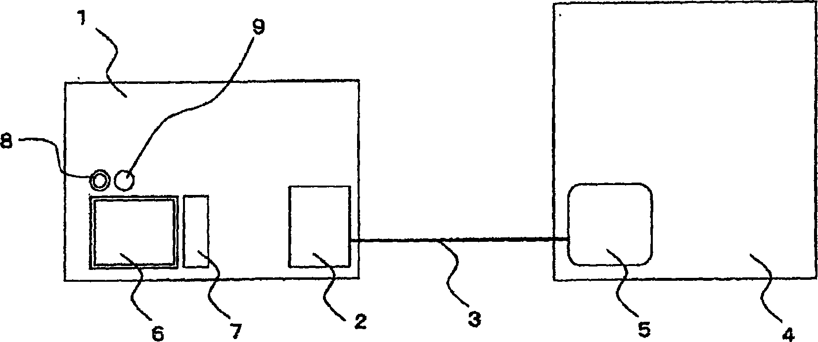
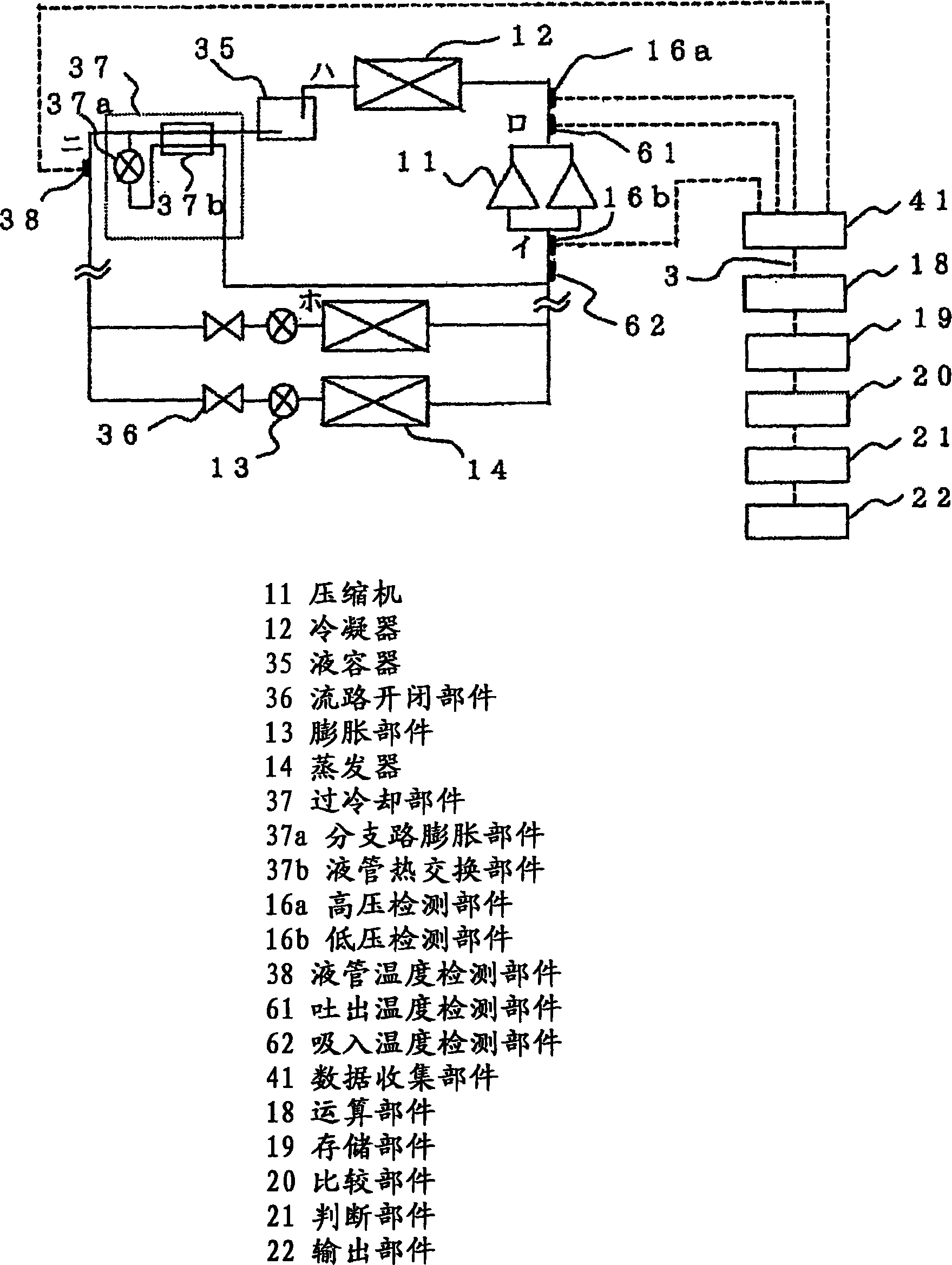
[0052] use Figure 1 to Figure 8 The configuration of Embodiment 1 of the present invention will be described. figure 1 It is an overall conceptual diagram of the present invention. 1 is a refrigeration cycle device such as a refrigerator or an air conditioner. Outputs such as warning lamps and substrates and microcomputers of devices for sending and receiving data to and from the outside, 3 are components for communicating with the outside such as telephone lines, local area network lines, and wireless, and 4 is for remote monitoring of the refrigeration cycle device 1 and The remote monitoring room for centralized management such as control, 5 is arranged in the remote monitoring room 4, and has the remote monitoring part that is used for displaying and computing functions of data transmission and reception with the refrigeration cycle device 1, that is, a computer, and 6 is set in the remote monitoring room 4. A display device such as a liquid crystal display in the refri...


PUM


Abstract

A failure diagnosis apparatus for a refrigerating cycle had a problem that it has a low precision because the fluid is treated, and it is difficult to detect a foretaste of failure, absorb individual differences of real machine in the failure determination, and determine a cause of failure. Also, no cheap and practical diagnosis apparatus and method are provided. A plurality of instrumentation amounts concerning the refrigerant such as the pressure and temperature of the refrigerating cycle apparatus or other instrumentation amounts are detected, the state quantities such as composite variables are acquired by making the arithmetic operation on these instrumentation amounts, and whether the apparatus is normal or abnormal is judged employing the arithmetic operation results. If learning is made during the normal operation, a current state is judged, and if learning is made by compulsorily performing the abnormal operation, or if the abnormal operating condition is operated during the current operation, a failure foretaste such as a critical operation can be made from a change in the Mahalanobis distance. Thereby, the secure diagnosis can be implemented with a simple constitution.

Description

technical field [0001] The present invention relates to technologies related to fault diagnosis and monitoring of equipment such as compressors of refrigerating cycle equipment used in refrigeration equipment and air-conditioning equipment, fluid circuits, blowers, and other equipment and equipment. Background technique [0002] As the fault diagnosis of air conditioners, the technology of taking control data such as sensors, set values, and abnormal signals, and then using operating data such as pressure and temperature to store the sequence of operating states under each fault in the microcomputer for fault diagnosis is available. proposal. Refer to Patent Document 1 (JP-A-2-110242 (FIGS. 4 to 11)). On the other hand, attempts to use the Mahalonobis distance as a multivariate analysis method are often made in fault diagnosis. In the past, the signal of the vibration sensor was compared with the normal state. Referring to Patent Document 2 (Japanese Unexamined Patent Publ...

Claims


Application Information

Patent Timeline
IPC IPC(8): F25B49/02F24F11/02G01M19/00F24F11/00F25B49/00G01M99/00
CPCF25B2400/13F25B2700/21163F25B2700/21151F25B2700/21152F24F2011/0091F25B2700/1933F25B2700/1931F25B49/005F25B2500/222F24F11/0086F24F11/30F24F11/52F24F11/38
Inventor 山下浩司丰岛正树中田浩
Owner MITSUBISHI ELECTRIC CORP
Why Eureka
Try Eureka