
Air-actuated plastic injection machine

An injection molding machine and pneumatic technology, which is applied in the field of pneumatic injection molding machines, can solve the problems that the equipment cannot be miniaturized, cannot meet the requirements of molding precision, and consumes a large amount of cooling water, so as to facilitate centralized management and maintenance, facilitate large-scale flow production, and save The effect of the production site

Inactive Publication Date: 2007-02-07
姚国卿
View PDF0 Cites 2 Cited by
  • Summary
  • Abstract
  • Description
  • Claims
  • Application Information

AI Technical Summary

Problems solved by technology

However, the power source of ordinary hydraulic injection molding machines is usually electric power, which is driven by centralized or decentralized motor power, and the hydraulic circuit transmits power; The force is so large that the products with small injection volume cannot meet the molding accuracy requirements. Moreover, the capital investment of a single ordinary hydraulic injection molding machine is large, the work efficiency is low, and there is a phenomenon of large horses and small carts; in addition, the use of ordinary injection molding machines that work completely through hydraulic methods , covers a large area, has high noise, and consumes a lot of cooling water for the equipment
Taking the smallest model of ordinary injection molding machine 150 as an example, the power of the equipment driving motor is 2.2KW / 380V, the electric heating power is 2KW, the total power consumption is 4.2KW, the equipment noise is 65dB, the cooling water consumption is 400 to 600 liters, and , when it is specially used for injection molding products with small injection volume, the equipment cannot be miniaturized, and it is impossible to manufacture a desktop compact injection molding machine with a weight of 250KG

Method used


Image

  • Air-actuated plastic injection machine
  • Air-actuated plastic injection machine
  • Air-actuated plastic injection machine

Examples


Embodiment Construction

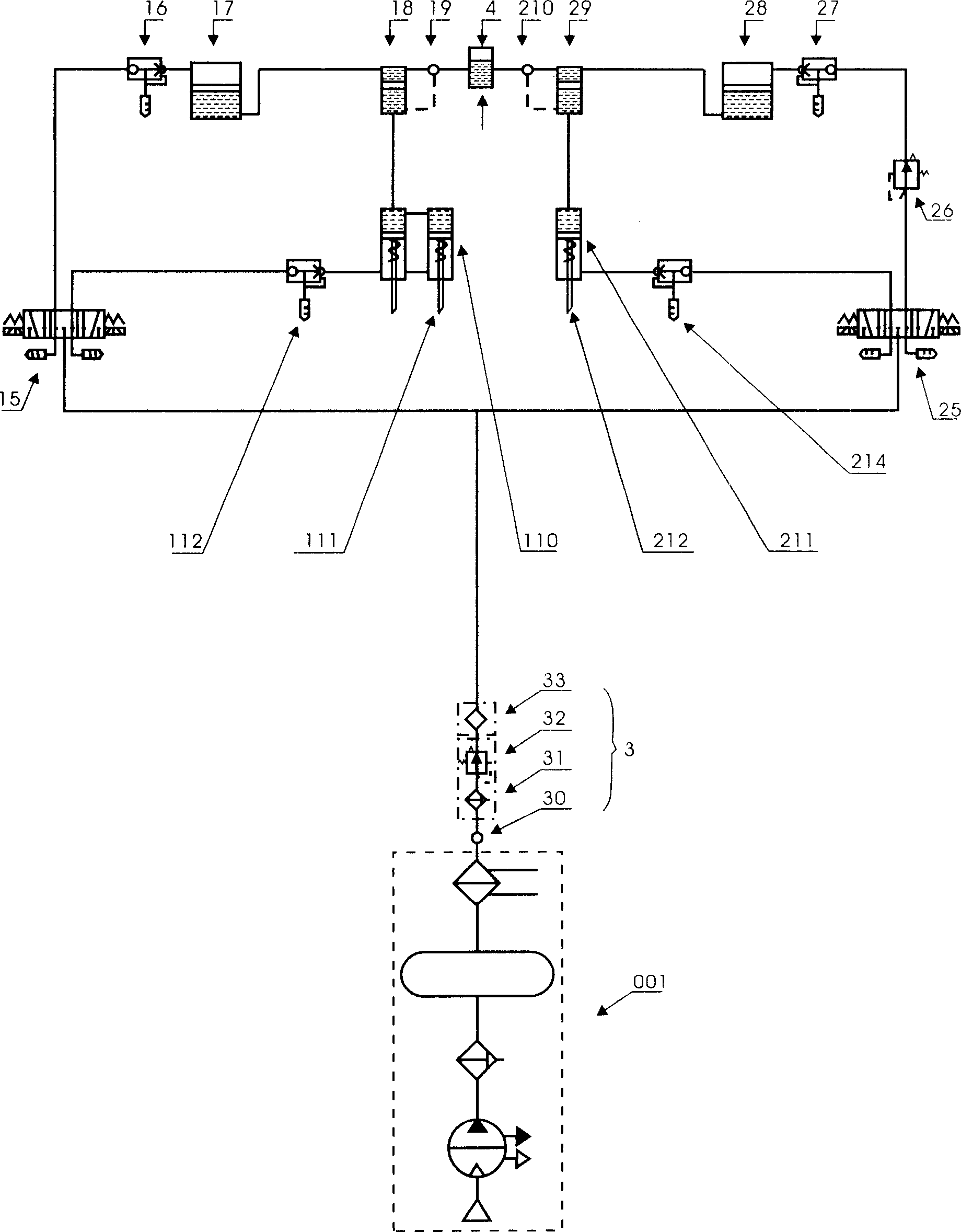
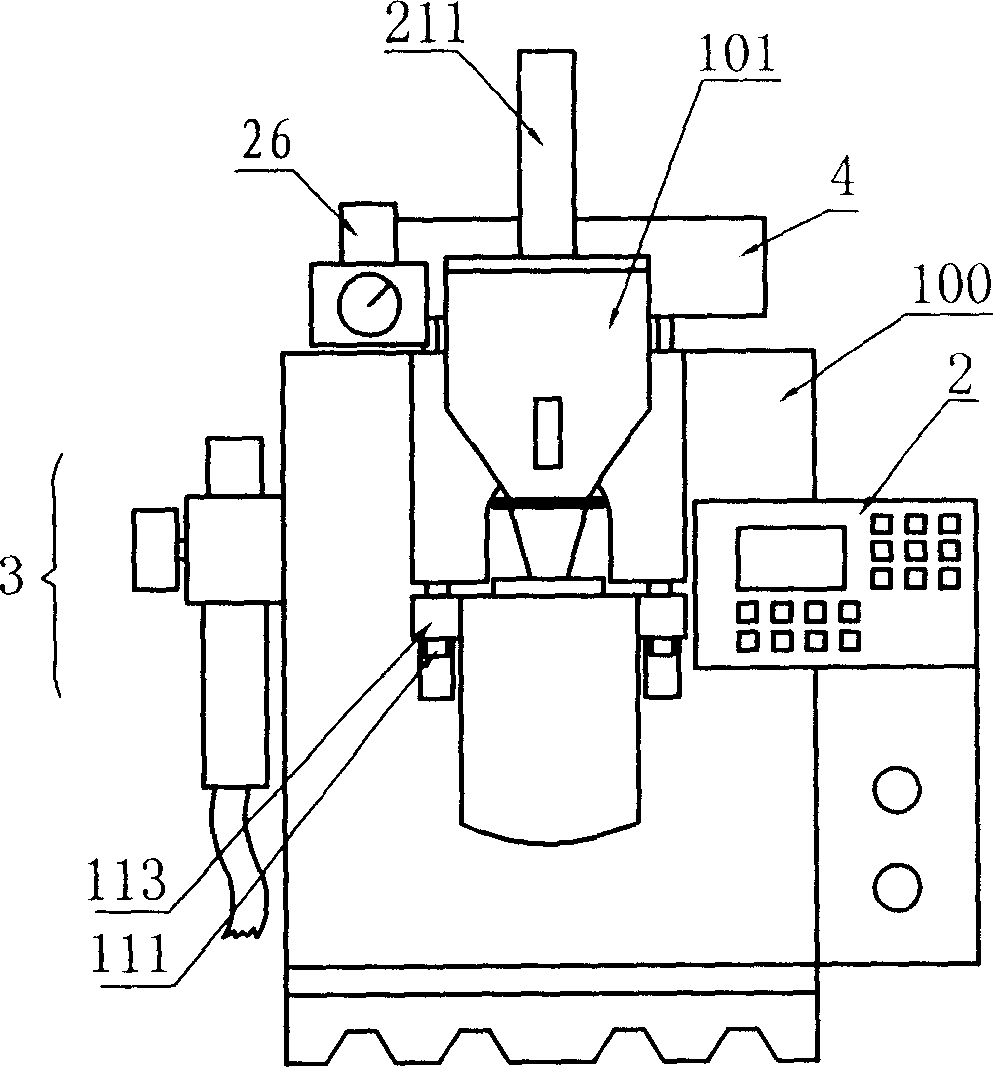
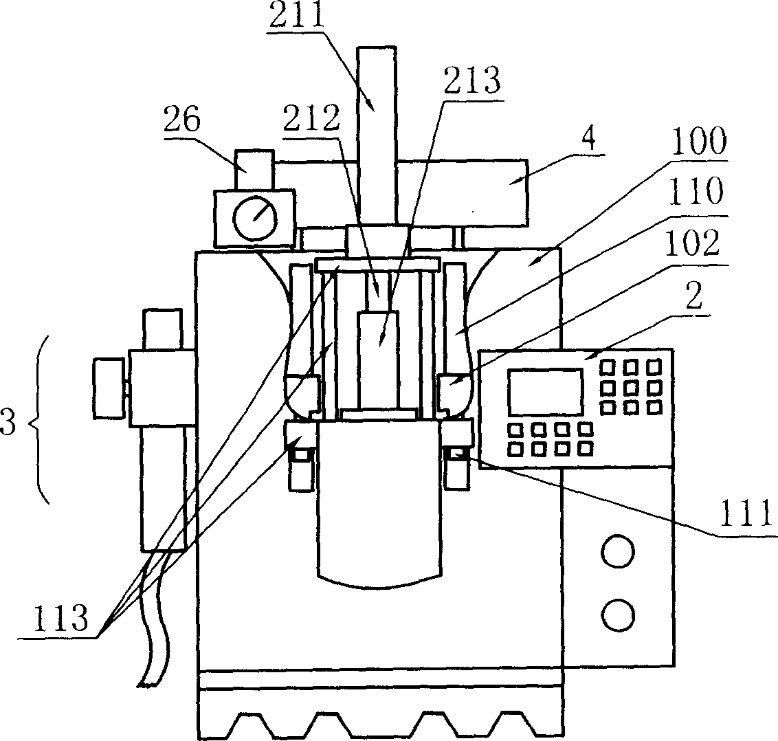
[0038] The following takes a vertical pneumatic injection molding machine as an example, combined with the schematic diagram of the connection of the pneumatic working parts of the pneumatic injection molding machine of the present invention and the accompanying drawings of the embodiment, the specific implementation of the pneumatic injection molding machine is described in detail;

[0039] figure 1 It is a schematic diagram of the pneumatic working parts and connections of the pneumatic injection molding machine of the present invention, and the pneumatic composition of the vertical pneumatic injection molding machine is also as follows figure 1 As shown, it includes an intake valve 30, a filter 3, a pneumatic injection / rod withdrawal branch, and a pneumatic mold opening / closing branch.

[0040] The intake valve 30 inputs the power compressed air pumped in by the central air pump station 001 after preliminary filtration, pressure stabilization and drying, and enters the filt...


PUM


Abstract

The invention relates to an air-powered injection machine, which uses compressed air as power source, via the conversation between air pressure and oil pressure and the boost of oil pressure, to use the hydraulic cylinder to complete the injection; said invention has low energy consumption, small volume and light weight; and it has high efficiency and simple operation; several devices can be parallel connected to use the central air source, to mould the small injection product lower than 15g.

Description

Technical field: [0001] The invention relates to an injection molding machine, in particular to a pneumatic injection molding machine with a relatively small injection volume for forming miniature injection molding products. Background technique: [0002] With the rapid development of electronics and communication technology, various electronic products with small injection molding plastic parts, such as IC packaging, or electronic and electrical accessories, and various terminal plug-ins or connectors are in great demand. However, the power source of ordinary hydraulic injection molding machines is usually electric power, which is driven by centralized or decentralized motor power, and the hydraulic circuit transmits power; The force is so large that the products with small injection volume cannot meet the molding accuracy requirements. Moreover, the capital investment of a single ordinary hydraulic injection molding machine is large, the work efficiency is low, and there i...

Claims


Application Information

Patent Timeline
IPC IPC(8): B29C45/82B29C45/67B29C45/17
Inventor 姚国卿
Owner 姚国卿
Learn More