Gaseous fuel injection valve

A gaseous fuel and injection valve technology, applied in fuel injection devices, special fuel injection devices, charging systems, etc., can solve problems such as reduced valve core opening responsiveness, reduce sucker effect, improve closing responsiveness, and reduce manufacturing cost effect

Active Publication Date: 2007-02-07
HITACHI ASTEMO LTD
View PDF1 Cites 11 Cited by
  • Summary
  • Abstract
  • Description
  • Claims
  • Application Information

AI Technical Summary

Problems solved by technology

Therefore, a small amount of lubricating oil is also mixed in the fuel supplied from the fuel tank to the injection valve. In the conventional gas fuel injection valve, if the lubricating oil adheres to the flat valve seat, especially the When the viscosity increases in the cold, when the valve core is seated on the valve seat, the above-mentioned lubricating oil induces a suction cup effect on the valve seat relative to the seated part, so when the coil is excited, it produces resistance to the seated part's separation from the valve seat, As a result, the opening response of the spool is reduced

Method used


Image

  • Gaseous fuel injection valve
  • Gaseous fuel injection valve
  • Gaseous fuel injection valve

Examples


Embodiment Construction

[0031] The implementation of the present invention will be described based on the preferred embodiments of the present invention shown in the accompanying drawings.

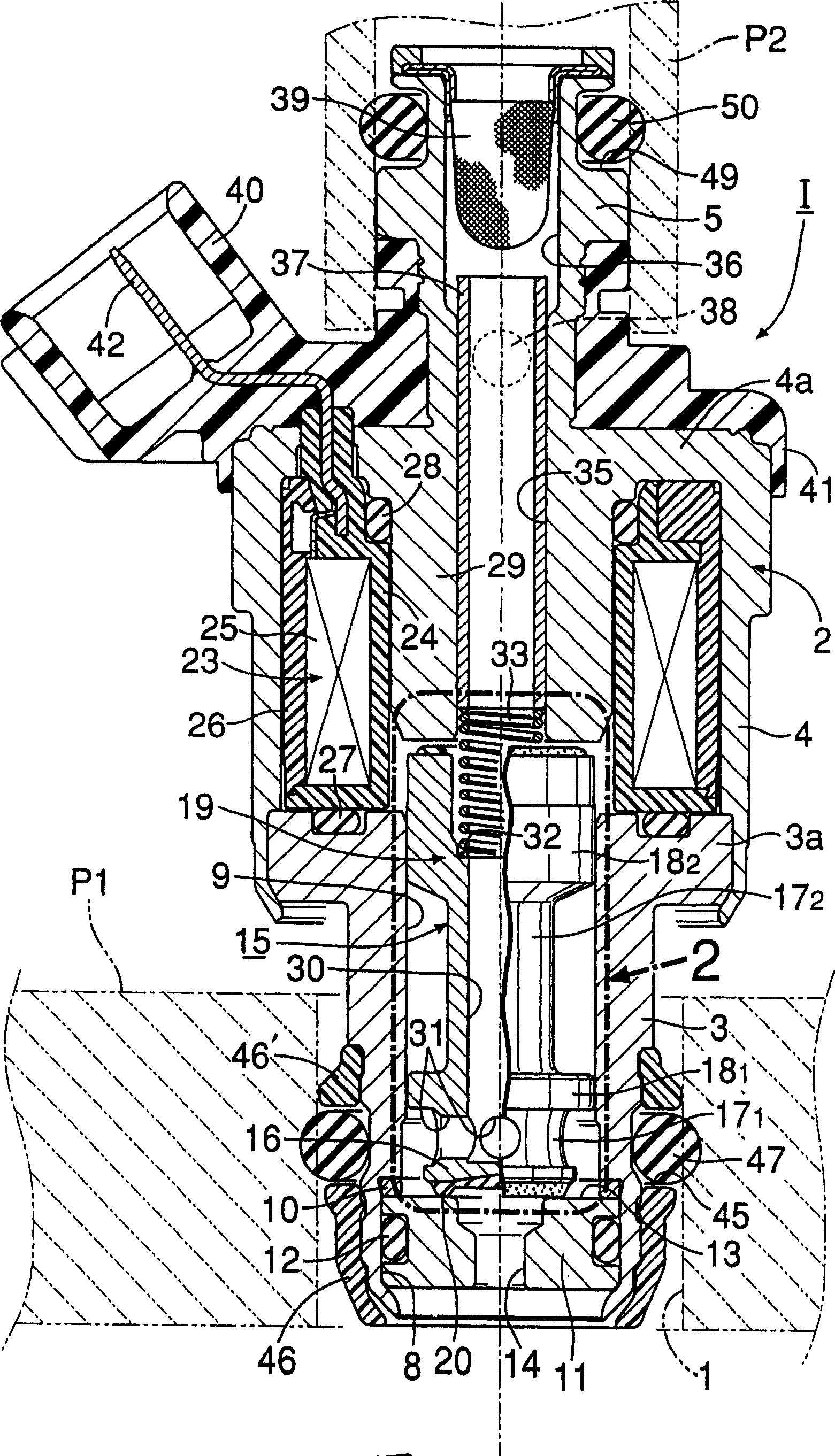
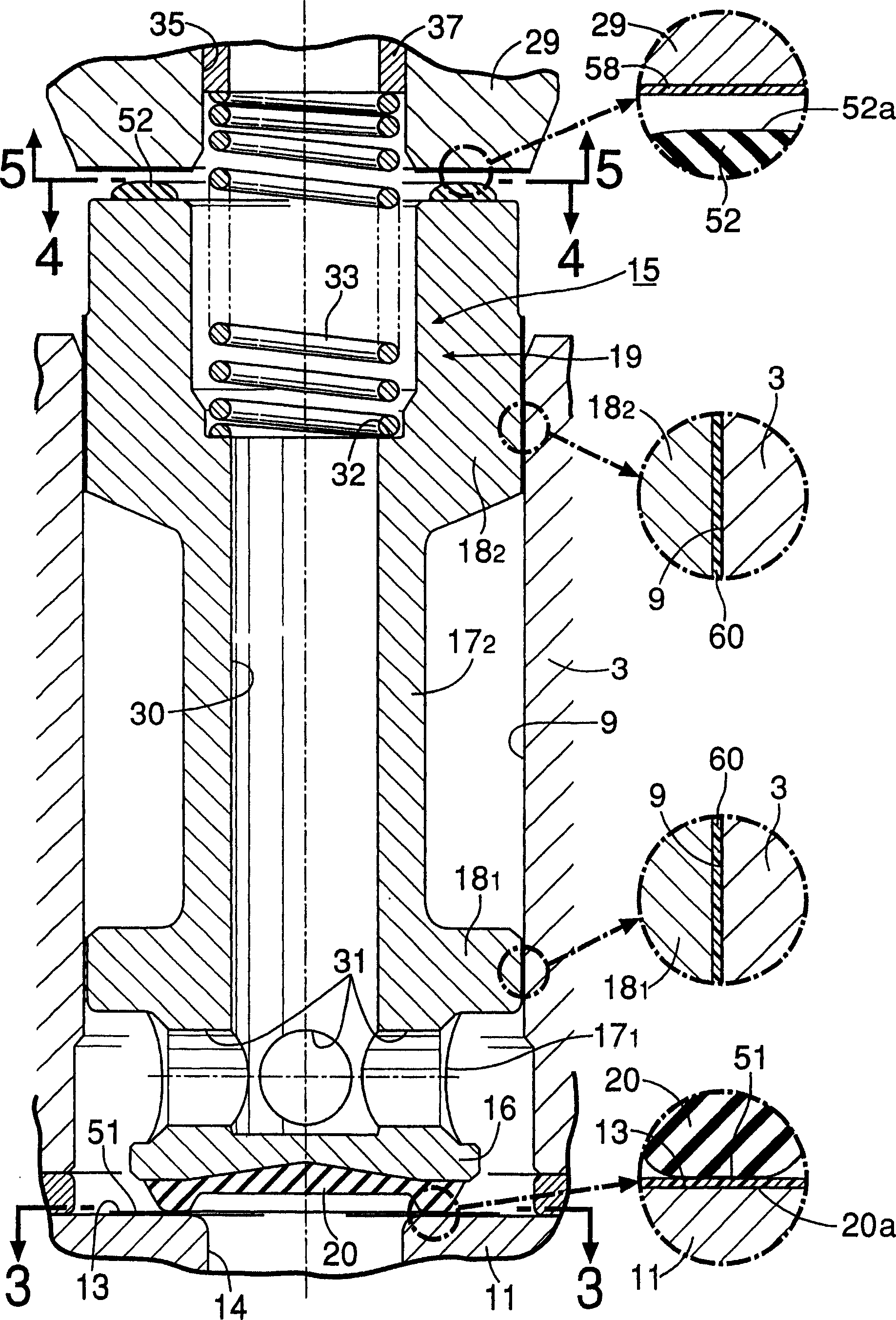
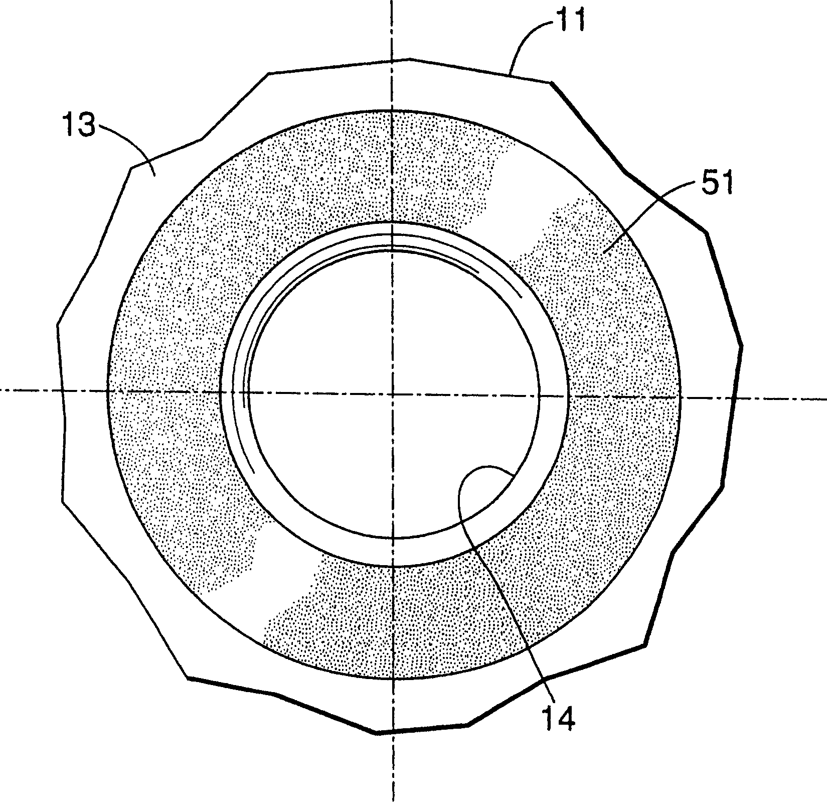
[0032] figure 1 It is a longitudinal sectional view of the gas fuel injection valve according to the first embodiment of the present invention. figure 2 yes figure 1 Enlarged view of 2 parts. image 3 yes figure 2 The 3-3 arrows point to the view. Figure 4 yes figure 2 The 4-4 arrows point to the view. Figure 5 yes figure 2 The 5-5 arrows point to the view. Figure 6 yes Figure 5 The three-dimensional view of the main part. Figure 7 yes Figure 4 The enlarged view of the 7-7 line section. Figure 8 represents the manufacturing process and Figure 7 corresponding figure. Figure 9 is the second embodiment of the present invention and figure 1 corresponding figure. Figure 10 It is a performance comparison line diagram of the injection valve related to the present invention and the convention...


PUM


Abstract

A gaseous fuel injection valve includes: a valve housing; a metallic nozzle member having a flat valve seat and a nozzle bore passing through a central portion of the valve seat; a valve body provided at one end face with a rubber seating member which is operated in cooperation with the valve seat; a coil; and a return spring for urging the valve body toward the valve seat. A stationary core attracts the valve body to move the seating member away form the valve seat, when the coil is excited. In this injection valve, a flourine resin valve seat coating is formed on the valve seat so that the seating members brought into close contact with the valve seat coating. Thus, an oil-repellent property of the valve seat coating is provided to the valve seat to prevent adherence of oil to the valve seat, leading to an improvement in valve-opening response of the valve body upon the excitation of the coil.

Description

technical field [0001] The present invention relates to an injection valve for gaseous fuel, which supplies natural gas such as CNG (compressed natural gas) and LPG (liquid propane gas; liquefied petroleum gas) as fuel to an internal combustion engine, and particularly relates to improvement of such an injection valve for gaseous fuel , that is, the injection valve for gaseous fuel comprises: a valve sleeve; a metal nozzle member fixedly arranged at one end of the valve sleeve and having a flat valve seat and a nozzle hole penetrating through the center of the valve seat; The valve core is embedded in the valve sleeve and has a rubber seating part that cooperates with the valve seat to open and close the nozzle hole on one end surface; the coil supported in the valve sleeve; and the valve sleeve a fixed iron core connected and arranged inside the coil and opposite to the other end surface of the valve core; The return spring, when the coil is energized, the fixed iron core at...

Claims


Application Information

Patent Timeline
Patent Type & Authority Applications(China)
IPC IPC(8): F02M21/02
CPCF02D19/024Y02T10/32F02M21/0266F02M2200/9038F02M21/0281F02M21/0254F02M61/166F02M51/0682F02M61/18Y02T10/30
Inventor 中岛要治泷口直人吉田崇
Owner HITACHI ASTEMO LTD
Why Eureka
Try Eureka